Fanuc Servo & Spindle Motor Common SV/AL Alarm Codes, Repair & CNC Maintenance
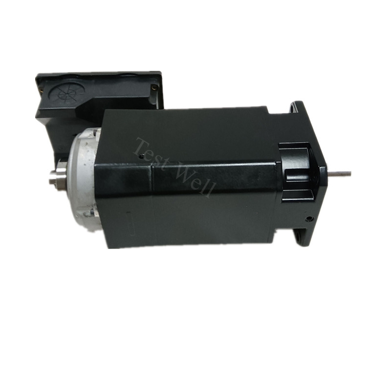
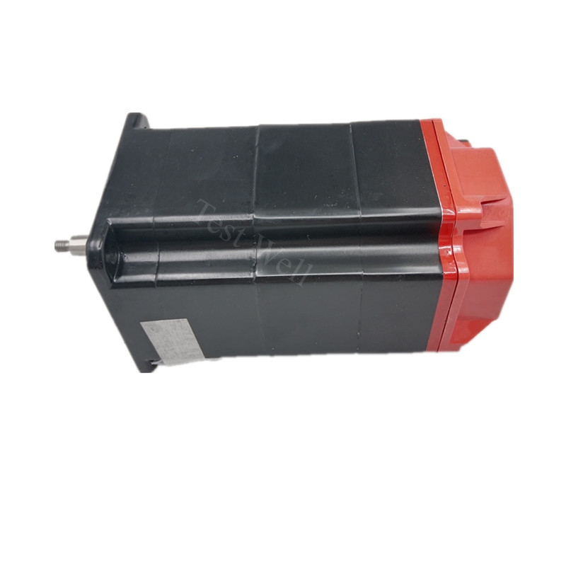
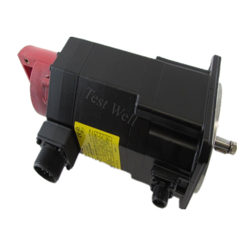
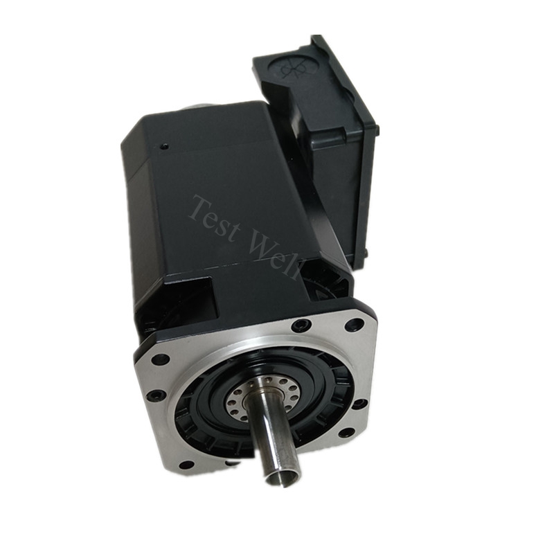
Fanuc AC servo motors (βi-B, αi-B, A06B series) and high-speed αi spindle motors are the core motion components of Fanuc 0i-MF, 31i, 32i CNC machining centers, lathes, mold machines and automation robotic cells worldwide. Equipped with high-resolution absolute pulse encoders, built-in thermal protection sensors, precision rolling bearings and integrated cooling structures, Fanuc motors deliver ultra-stable positioning accuracy, heavy cutting torque and long continuous operating life in harsh workshop environments filled with metal dust, cutting fluid and oil mist.
Even premium Fanuc motors frequently trigger CNC servo SV alarms or spindle AL trip faults caused by clogged cooling passages, worn bearings, expired absolute encoder backup batteries, damaged JYA/JYB feedback cables, mechanical axis jamming, excessive cutting load, loose connectors and skipped routine maintenance. More than 80% of CNC production downtime originates from misjudging motor overheating, encoder communication loss, speed detection failure and overload faults, rather than original manufacturing defects. This comprehensive SEO technical guide covers Fanuc motor system composition, fast on-site symptom identification, mainstream official SV servo / AL spindle alarm code troubleshooting, standardized professional repair workflows and tiered full-cycle preventive maintenance plans, helping global CNC maintenance technicians rapidly locate and resolve motor failures.
Please check our Fanuc αi/βi Servo & Spindle Motor Full Series Page.
1. Core System Structure & Fault Classification of Fanuc Motor System
A complete Fanuc closed-loop motion control system includes three core parts: servo/spindle motor body, built-in absolute pulse encoder, and matching servo/spindle amplifier unit.
- Motor Mechanical Body: Consists of stator winding, rotor shaft, precision bearings, shaft oil seal, built-in cooling fan and thermal temperature sensor; prone to overheating, abnormal vibration, grinding noise and overload faults.
- Absolute Pulse Encoder (Rear Shaft Mounted): Transmits real-time position and speed feedback signals to amplifier via JYA (power) / JYB (signal) cables; powered by backup lithium battery when CNC main power cuts off, triggers low-battery and communication loss alarms once damaged.
- Servo / Spindle Amplifier Unit: Receives CNC motion commands and encoder feedback signals to form closed-loop control; all motor-side abnormal conditions are converted into SV servo alarms or AL spindle two-digit alarm codes displayed on the CNC screen or amplifier panel.
All Fanuc motor related industrial faults fall into four clear categories for targeted troubleshooting:
- Thermal Overload Faults: SV0430 servo motor overheat, AL01 spindle motor overheat, long-term heavy cutting load, blocked cooling air channel, failed built-in cooling fan
- Encoder Feedback & Battery Faults: Low absolute encoder battery warning, encoder signal loss, JYA/JYB cable breakage, loose encoder connector, positioning drift after power cycle
- Mechanical Bearing & Load Faults: Abnormal grinding vibration noise, axis mechanical jamming, coupling eccentricity, shaft seal oil leakage, AL31 spindle speed detection failure
- Communication & System Circuit Faults: SV0401 VRDY ready signal loss, FSSB bus communication timeout, loose power UVW terminals, EMI interference causing random axis offset
2. Fast Preliminary Fault Diagnosis via Operating Symptoms & CNC Alarm Codes
Fanuc CNC systems display SV four-digit servo alarms for axis servo motors and two-digit AL alarms for spindle motors once protective shutdown activates. Technicians can classify fault sources instantly before disassembly and testing without professional testing equipment:
Typical Fanuc Motor Failure Manifestations
- CNC screen pops up SV0430 / amplifier AL01, motor surface extremely hot after short cutting cycles → Motor thermal overload or blocked cooling system
- Machine loses axis zero origin after power off, CNC pops low encoder battery reminder → Absolute encoder backup battery voltage depleted
- Spindle cannot reach commanded RPM, amplifier shows AL31 speed detection error → Damaged spindle speed sensor or broken feedback cable
- Axis generates regular grinding noise and violent vibration during reciprocating movement → Worn motor bearings or misaligned mechanical coupling
- Random axis positioning drift without fixed alarms, inconsistent machining dimensions → Encoder cable shielding damage or electromagnetic interference
- CNC triggers SV0401 VRDY loss alarm immediately after power-on → Loose motor UVW power cable or broken JYA/JYB feedback connector
3. Most Common Fanuc Motor SV Servo & AL Spindle Alarm Codes & Step-by-Step Repair Solutions
Combined with official Fanuc maintenance manuals (B-65285EN) and high-frequency CNC workshop failure cases, we sort core alarm codes, root causes and operable standardized repair steps for αi / βi servo and αi spindle motor series.
3.1 SV0430 Servo Motor Overheat Alarm (Most Frequent Servo Motor Fault)
Fault Manifestations: CNC screen displays SV0430, axis automatically slows down or trips to fault state; Diagnosis No.308 shows motor temperature exceeds 120°CPLC论坛 Root Causes:
- Long-term heavy cutting load exceeding motor continuous torque rating
- Motor built-in cooling fan stuck or broken, cooling air channel blocked by metal powder and cutting sludge
- Mechanical guide rail jamming leading to sustained extra friction load
- Damaged internal thermal detection sensor inside motor rear housing Repair Steps:
- Stop all cutting programs, lockout-tagout total machine power and wait 30 minutes for full motor cooling
- Remove motor rear cooling cover, clean all metal debris blocking air passages with low-pressure dry compressed air
- Manually spin built-in cooling fan blade; replace genuine Fanuc cooling fan assembly if stuck or producing grinding noise
- Disconnect mechanical coupling and test motor no-load rotation; if alarm disappears, troubleshoot tight guide rails, ball screw or stuck tool holders
- Access CNC parameter screen to optimize cutting feed speed and depth to reduce sustained heavy load cycles
- If temperature reading on DGN308 remains abnormally high under no-load operation, replace the complete servo motor (thermal sensor integrated non-separably inside motor housing)
3.2 AL01 Spindle Motor Overheat Alarm
Fault Manifestations: Spindle amplifier red ALM light illuminates, two-digit display shows AL01; spindle speed limited automaticallyTIE Inform... Root Causes:
- Excessive heavy-duty milling cutting load, continuous high-RPM operation without cooling intervals
- Liquid cooling spindle: clogged cooling water pipeline, insufficient coolant flow or dirty filter
- Air-cooled spindle: blocked cooling fins, failed external cooling blower
- Loose JY1/JY2 thermal sensor connector on spindle amplifier terminal block Repair Steps:
- Power off spindle amplifier and wait for motor temperature to drop below 60°C before inspection
- Clean spindle cooling filter screen, unclog blocked water pipelines and check coolant pump operating status for liquid-cooled models
- Tighten JY1/JY2 thermal detection wiring terminals on the spindle SPM amplifier unit
- Reduce long-duration full-load high-speed cutting cycles to match spindle rated duty cycle
- Replace spindle motor internal thermal switch if alarm recurs under light no-load operation
3.3 Absolute Encoder Low Battery Warning & Position Data Loss Fault
Fault Manifestations: CNC pops battery low warning on boot; machine loses zero return origin position after every power cycle, random axis offset occurs during machining Root Causes:
- Absolute encoder dedicated lithium backup battery service life expired (standard lifespan 1–2 years)
- Loose battery holder terminals inside electrical cabinet or motor encoder housing
- Damaged JYA encoder power supply cable causing unstable voltage supply to encoder chip Repair Steps:
- Keep the entire CNC machine powered ON during battery hot swap to avoid permanent loss of axis origin offset data
- Remove old exhausted battery and install genuine Fanuc matching replacement lithium battery pack
- Tighten battery holder wiring terminals and inspect JYA encoder power cable for cracks or abrasion
- Perform full axis zero return calibration after battery replacement, back up all workpiece coordinate offset data to CNC memory
- Schedule quarterly battery voltage inspection to prevent sudden position data loss during production shifts
3.4 AL31 Spindle Speed Detection Failure Alarm
Fault Manifestations: Spindle refuses to rotate or runs at extremely low RPM, spindle amplifier displays AL31 speed sensor errorCNC Electr... Root Causes:
- Broken spindle speed feedback wire between motor and SPM amplifier
- Speed sensor mounted loose or contaminated with cutting oil and metal dust
- Incorrect spindle speed detection parameter settings in CNC parameter No.4001
- Internal speed sensor chip damage integrated inside spindle motor rear cover Repair Steps:
- Cut machine power, unplug and reinsert spindle feedback signal connectors on both motor and amplifier sides
- Clean speed sensor surface oil sludge and metal powder with lint-free alcohol cloth
- Verify CNC spindle parameter No.4001 bit 4 polarity setting matches sensor installation direction
- Test spindle operation after parameter correction; replace spindle motor if alarm persists after cable and parameter adjustment
3.5 Abnormal Bearing Vibration & Grinding Noise (No Fixed Alarm Code)
Fault Manifestations: Axis generates continuous metal grinding sound during reciprocating movement, obvious vibration leads to inconsistent workpiece dimensional tolerance Root Causes:
- Motor front/rear precision bearings worn after long high-cycle operation
- Insufficient or deteriorated high-temperature bearing lubricating grease
- Coupling concentricity offset between motor shaft and ball screw
- Motor rear shaft seal aging, cutting fluid seeping into bearing cavity causing corrosion Repair Steps:
- Power off equipment, manually rotate motor shaft by hand; rough, jerky rotation confirms bearing failure
- Disassemble motor front and rear end caps, remove old bearings and replace with original Fanuc precision bearing kits
- Refill high-temperature resistant lubricating grease matching Fanuc motor specification
- Replace aged shaft oil seal to block cutting fluid and oil mist from entering internal motor components
- Re-calibrate coupling concentricity to eliminate eccentric vibration during high-speed movement
3.6 SV0401 VRDY Servo Ready Signal Loss Alarm
Fault Manifestations: CNC triggers SV0401 alarm immediately after power-up, servo axis cannot enable, machine locks out all motion functionsCMTR Root Causes:
- Loose UVW three-phase motor power terminals on servo amplifier CN1 connector
- Damaged JYB encoder feedback cable between motor rear encoder and amplifier CN2 port
- Blown servo power supply fuse or tripped cabinet circuit breaker
- Emergency stop E-stop circuit chain broken, cutting off servo VRDY signal loop Repair Steps:
- Check all machine emergency stop buttons and door safety interlocks to ensure full E-stop circuit closure
- Inspect servo power cabinet fuses and circuit breakers; replace blown fuses with original specification parts
- Unplug and re-seat CN1 motor power connector and CN2 JYB encoder connector on servo amplifier
- Swap a confirmed intact JYB feedback cable to verify cable breakage and replace damaged wiring harness
Please check our Fanuc Motor Spare Parts Page.
4. Standard Professional Fanuc Servo & Spindle Motor Repair Workflow
Follow this standardized Fanuc official safety troubleshooting sequence to avoid blind disassembly, permanent encoder data loss and secondary hardware damage:
- Fault Record & Preliminary Classification: Record CNC SV/AL alarm codes, abnormal noise/vibration, motor surface temperature and failure trigger conditions; separate thermal overload, encoder battery, mechanical bearing and communication cable fault categories
- Full LOTO Power-Off Inspection: Cut total CNC main power, wait minimum 15 minutes for servo/SPM amplifier DC bus capacitors to fully discharge; visually inspect motor UVW power cables, JYA/JYB encoder connectors, cooling fan, shaft seal oil leakage and dust accumulation
- CNC Software Diagnostic Capture: Enter CNC diagnostic screen to read DGN308 motor temperature, encoder battery voltage and servo current waveform; fully back up all CNC programs, workpiece offsets and axis parameter files before hardware disassembly
- Isolation Cross-Test Verification: Disconnect mechanical coupling to run motor no-load test to separate mechanical load faults from motor body defects; swap intact JYA/JYB cables and batteries to isolate encoder wiring and power supply faults
- Targeted Parts Replacement & Calibration: Replace expired batteries, broken feedback cables, worn bearings or cooling fans with 100% genuine Fanuc spare parts; re-calibrate spindle speed parameters, servo gain values and full axis zero origin after repair
- Full CNC Production Cycle Validation: Reconnect all wiring securely, power on CNC system, complete axis zero return, run continuous automatic cutting cycles to confirm all alarms, vibration and positioning drift faults are fully eliminated
5. Full-Cycle Preventive Maintenance Schedule for Fanuc CNC Motors
Scientific regular maintenance eliminates over 80% of sudden Fanuc motor CNC alarms and extends bearing, encoder and cooling fan service life by more than 35%. This maintenance plan complies with Fanuc factory environmental specifications (operating ambient temperature 0–40°C, non-condensing humidity without oil mist accumulation)reacocnc.c....
5.1 Daily CNC Operator Routine Inspection
- Check CNC operation screen for SV servo, AL spindle alarms and low encoder battery warning reminders
- Listen to servo and spindle motor rotation sound for abnormal grinding, rattling or buzzing noise
- Touch motor housing surface to monitor excessive overheating during continuous cutting shifts
- Visually inspect JYA/JYB encoder cables and UVW power cables in drag chains for scratches, oil corrosion and hard bending fatigue
- Confirm no cutting fluid, metal filings or oil mist accumulates on motor rear encoder housing and cooling air vents
5.2 Weekly Maintenance
- Wipe motor outer casing, encoder cover and cooling vent filters with dry lint-free cloth to keep unobstructed cooling airflow
- Tighten all motor power UVW terminal screws and JYA/JYB encoder connector locking clamps
- Reorganize drag chain wiring layout to separate high-power motor UVW cables and weak encoder signal cables for EMC anti-interference
- Clean debris blocking motor cooling air intake and exhaust passages
5.3 Quarterly Deep Maintenance
- Power down the entire CNC machine, blow internal motor cooling channel and encoder housing dust with low-pressure dry compressed air (avoid high-pressure air damaging delicate encoder optical components)
- Test absolute encoder backup battery voltage with multimeter; pre-schedule battery replacement for low-voltage units
- Inspect motor shaft oil seal for cutting fluid leakage; replace aged seals to prevent internal component corrosion
- Fully back up all CNC program, offset and parameter data to external USB storage
- Test servo and spindle communication signal stability via CNC diagnostic waveform screen
5.4 Annual Professional Complete Overhaul
- Replace absolute encoder lithium backup batteries uniformly every 12–24 months to avoid sudden position data loss
- Disassemble motor front/rear end caps, inspect bearing wear status; replace bearing kits after 20,000+ operating hours
- Replace drag chain JYA/JYB flexible encoder cables prone to repeated bending fatigue damage
- Clean spindle speed sensor and encoder optical disk surface oil and metal dust contamination
- Update CNC and amplifier firmware to latest Fanuc official compatible versions to resolve known system bugs
- Test cabinet grounding resistance to ensure earth ground impedance below 5 ohms for anti-EMI interference
5.5 Long-Term Idle Storage Maintenance
Store unused Fanuc servo/spindle motors in dry, dust-free, constant-temperature warehouses free of corrosive cutting fluid vapor. Power on the matching CNC and run each motor at low speed for 20 minutes every month to prevent encoder battery self-discharge and circuit board moisture corrosion. Do not apply heavy pressure to motor rear encoder housing to avoid optical disk deformation.
6. Clear Distinction: Fanuc Motor Hardware Fault vs Mechanical Axis Load Fault vs CNC Parameter Configuration Fault
Accurate fault classification drastically shortens CNC maintenance downtime; compare core distinguishing characteristics below:
Fanuc Servo/Spindle Motor Hardware Fault Features
- Fixed SV/AL alarm codes appear on CNC screen even when mechanical coupling is fully disconnected
- Visible physical damage: worn bearings, leaking shaft seals, cracked encoder cables, dead cooling fans
- Faults cannot be eliminated by adjusting CNC cutting feed, acceleration or spindle speed parameters
Mechanical Axis Load Fault Features
- No persistent motor alarms during motor no-load operation; SV/AL trip faults only activate after connecting ball screw, coupling and workpiece load
- Obvious mechanical jamming, tight guide rails or heavy workpiece weight leads to motor overload overheating
- Abnormal vibration and grinding noise disappears immediately after decoupling motor from transmission mechanism
CNC Parameter Configuration Fault Features
- Motor hardware operates normally without overheating, noise or physical damage
- Alarms only trigger under specific cutting speed, feed rate or spindle RPM cycle conditions
- Faults vanish instantly after correcting spindle speed detection parameters, servo gain or acceleration ramp values
Conclusion
Fanuc αi/βi servo and αi spindle motors are high-precision core motion components of CNC machining equipment, yet most daily SV/AL trip faults such as motor overheating, encoder battery failure, speed detection error and abnormal vibration originate from neglected cooling cleaning, expired consumable parts, loose wiring terminals and mismatched CNC parameter settings, not manufacturing quality defects. Mastering CNC SV/AL alarm code diagnosis, no-load isolation test methods and tiered daily/quarterly/annual maintenance schedules can drastically reduce factory unplanned CNC downtime and maintenance labor costs.