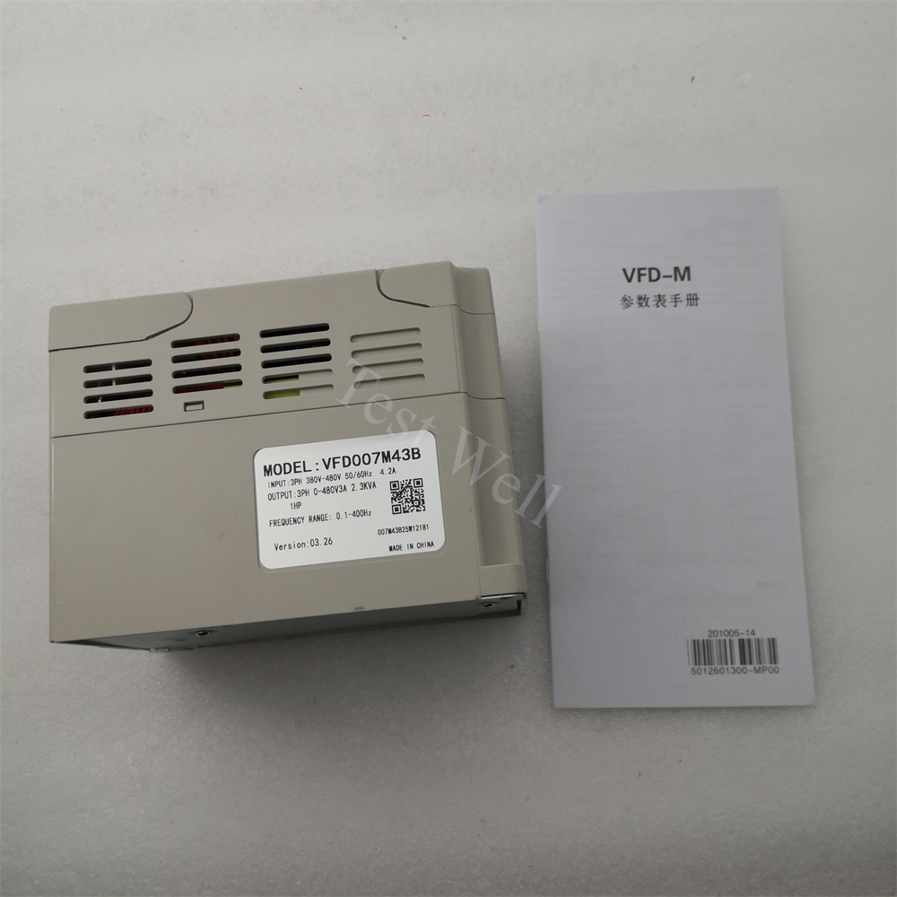
Delta Inverter Troubleshooting: Fault Codes, Step-by-Step Repair & Full Preventive Maintenance Guide
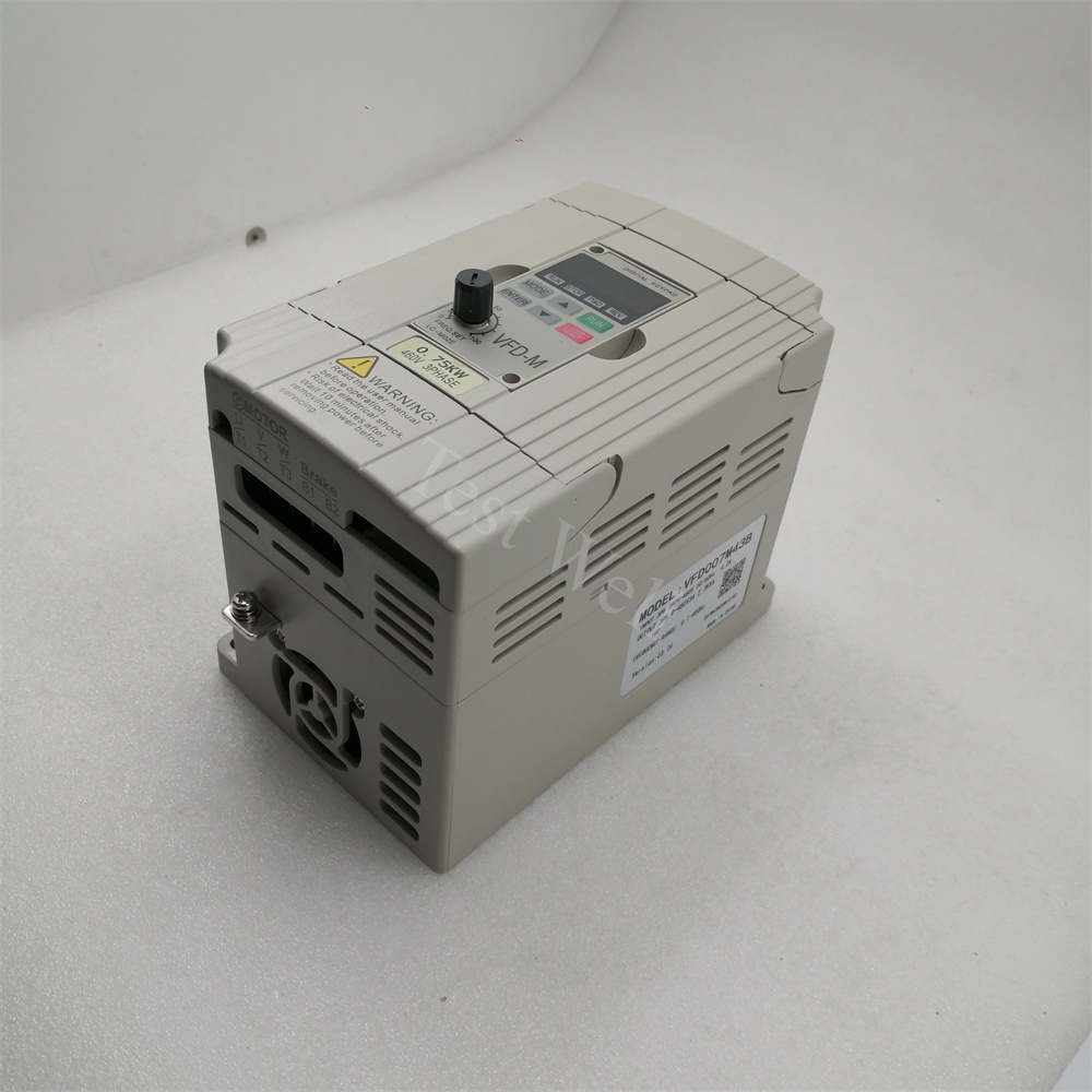
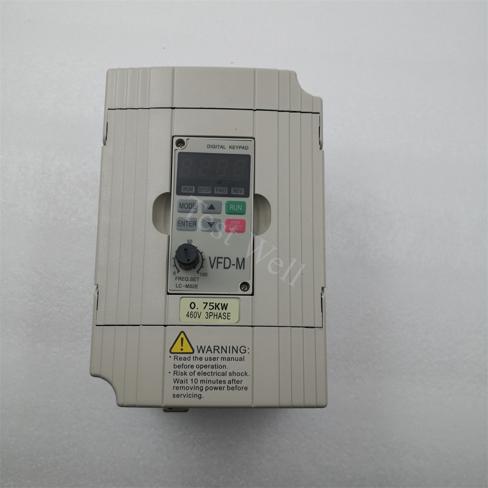
Delta Electronics variable frequency drives (compact MS300, general-purpose VFD-EL/VFD-E, heavy-duty CP2000, high-performance CH2000 series) are globally adopted for speed regulation of fans, water pumps, conveyor belts, packaging machinery, CNC equipment, cranes and process automation production lines. Designed with advanced vector control, built-in Modbus RS485 communication and multi-layer hardware protection logic, Delta inverters deliver stable torque output, outstanding energy-saving efficiency and long service life in dusty, humid, oil mist industrial workshop environments.
Even high-quality Delta VFDs frequently trigger protective trip faults caused by dust-clogged heat sinks, aging cooling fans, degraded DC bus smoothing capacitors, mechanical load jamming, unstable industrial grid power, poor EMC wiring shielding and ignored regular maintenance. More than 70% of unplanned production downtime originates from misjudging overcurrent, DC overvoltage, heatsink overtemperature, ground leakage, input phase loss and Modbus communication faults, rather than inherent manufacturing hardware defects. This comprehensive SEO technical guide covers Delta inverter system composition, fast on-site symptom identification, mainstream official alphanumeric fault code troubleshooting, standardized professional repair workflows and tiered full-cycle preventive maintenance plans, helping worldwide maintenance technicians rapidly locate and resolve VFD failuresManualsLib.
Please check our Delta VFD Inverter Page.
1. Core System Structure & Fault Classification of Delta VFD Drives
A complete Delta variable frequency drive system consists of four core functional units to regulate three-phase induction and permanent magnet synchronous motors:
- Input Rectifier Module: Converts AC mains into stable DC voltage stored on DC bus capacitors; prone to Lv/UV undervoltage and OrP input phase loss faults triggered by grid fluctuation, blown fuses or loose R/S/T power terminal
- DC Bus Capacitor Bank: Balances voltage ripple and absorbs motor regenerative braking energy; bulging, leaking capacitors trigger recurring OV overvoltage faults after 5–8 years of continuous operationHL Auto.
- IGBT Inverter Power Stage: Converts DC power to adjustable PWM AC for motor speed and torque control; short circuits and heavy overloads burn IGBT chips, triggering OC series overcurrent and GFF ground leakage faults...
- Control & Cooling System: Mainboard logic circuit processes parameter configuration, Modbus communication and protective signal detection; cooling fans and aluminum heat sinks prevent IGBT overheating and OH1/OH3 overtemperature tripsDelta.
All Delta industrial VFD faults fall into four clear categories for targeted troubleshooting:
- Electrical Power & IGBT Faults: oCA/oCd/oCN overcurrent, GFF ground leakage, OrP input phase loss, oVA/oVd/oVN DC overvoltage, LvA/Lvd/Lvn DC undervoltage
- Thermal Cooling Faults: OH1 IGBT heatsink overheat, OH3 motor overtemperature, tH1o temperature detection failure, stuck cooling fan, blocked ventilation and high ambient temperature alarms
- Motor & Mechanical Load Faults: oL drive overload, EoL1/EoL2 electronic thermal relay trip, motor stall, mismatched motor nameplate parameters, incomplete auto-tuning
- Communication & System Faults: CE1/CE2/CE3 Modbus communication timeout, parameter memory error, external interlock trip, EMI electromagnetic signal interferenceManualsLib
2. Fast Preliminary Fault Diagnosis via Operating Symptoms & Alphanumeric Fault Codes
All Delta MS300, CP2000, CH2000 and VFD-EL series inverters display standardized two/three-letter fault codes on the front digital keypad once protective shutdown activates. Technicians can classify fault sources instantly before disassembly and testingManualsLib:
Typical Delta VFD Failure Manifestations
- Immediate trip on power-up, panel shows oCA / oCd / oCN / GFF → Motor cable short circuit, ground leakage or damaged internal IGBT module
- Alarm triggers during machine deceleration, oVd/oVN overvoltage displayed → Excessive regenerative energy without matched braking resistor unit
- Drive casing extremely hot, continuous OH1 overtemperature warning → Clogged heat sink, stuck cooling fan or ambient temperature exceeding 40°C
- Motor runs slowly with heavy vibration, frequent oL/EoL overload trips → Mechanical load blockage or incorrect motor rated current Pr.07 parameters
- No fixed fault code but unstable motor speed, random stalling → Poor cable shielding, electromagnetic interference or aged DC bus capacitors
- HMI/PLC offline, Modbus communication loss → Damaged RS485 cable, mismatched baud rate or conflicting slave station addresses
3. Most Common Delta VFD Fault Codes & Step-by-Step Repair Solutions
Combined with official Delta operation manuals and high-frequency on-site workshop failures, we sort core error codes, root causes and operable repair steps for mainstream Delta drive series.
3.1 oCA / oCd / oCN Overcurrent Fault (Acceleration / Deceleration / Constant Speed)
Fault Manifestations: Drive trips instantly during startup, deceleration or steady running; output current exceeds 200% of rated drive threshold Root Causes:
- U/V/W motor output cable phase-to-phase short circuit or insulation breakdown to ground
- Motor winding internal short circuit or locked rotor mechanical jam
- Overly short acceleration (Pr.01-10) and deceleration (Pr.01-11) ramp parameters
- Damaged internal IGBT power modules or current detection Hall sensors Repair Steps:
- Execute full lockout-tagout (LOTO), cut main AC power and wait minimum 10 minutes for DC bus capacitors to fully discharge to avoid electric shock hazards
- Disconnect all U/V/W motor cables and perform no-load power-on test; if OC fault disappears, the defect belongs to motor or output wiring
- Test motor winding insulation with a 500V megohmmeter; replace motors with insulation resistance below 1MΩ
- Extend acceleration Pr.01-10 and deceleration Pr.01-11 time parameters via the digital keypad
- Inspect main circuit board for burn discoloration; replace genuine Delta IGBT modules if hardware damage is confirmed
- Separate power cables from signal control wires and install ferrite magnetic rings to reduce transient current interference
3.2 oVA / oVd / oVN DC Link Overvoltage Fault
Fault Manifestations: Alarm activates during acceleration, deceleration or inertial load operation; DC bus voltage exceeds safety threshold (800VDC for 400V-class drives) Root Causes:
- Fast deceleration generates massive regenerative energy without matched braking resistor
- Unstable high industrial grid input voltage surges
- Heavy inertial loads (conveyors, cranes, centrifugal fans) feeding excess voltage back to the DC bus
- Aging DC bus capacitors with reduced energy absorption capacity Repair Steps:
- Increase deceleration Pr.01-11 ramp time parameters to slow regenerative energy feedback speed
- Install genuine Delta matched braking resistor at P/+ and DB terminals for high-inertia equipment
- Add input line reactors or voltage stabilizers for factories with severe mains fluctuation
- Power off and inspect DC bus capacitor banks for bulging casing, liquid leakage or discoloration; replace aged capacitor sets completely
- Reduce frequent cyclic start-stop operation cycles to cut repeated regenerative voltage surges
3.3 LvA / Lvd / Lvn DC Link Undervoltage / OrP Input Phase Loss
Fault Manifestations: Drive fails to start or randomly shuts down mid-operation; DC bus voltage drops below detection limit, OrP alarm shows three-phase power imbalance Root Causes:
- Three-phase input power phase loss, loose R/S/T input terminals or oxidized wiring lugs
- Blown input main fuse or damaged rectifier bridge diodes
- Severe grid voltage drop during factory peak power consumption hours Repair Steps:
- Measure three-phase input AC voltage with a multimeter to identify phase loss or low voltage phases
- Tighten all input power terminal screws with standard torque and replace corroded cable lugs
- Inspect input fuses and rectifier modules; replace blown fuses and damaged rectifier components
- Avoid sharing the same power transformer with large welding machines or heavy impulse machinery
3.4 GFF Ground Leakage Fault
Fault Manifestations: Drive trips immediately after connecting motor output cables; excessive ground leakage current detected, ground protection triggered Root Causes:
- Motor power cable insulation worn through and touching metal cabinet ground
- Motor winding internal ground short circuit
- Oil mist, metal dust and cutting fluid corroding terminal block insulation Repair Steps:
- Disconnect U/V/W output cables one phase at a time to isolate the leakage phase
- Replace cracked, oil-corrupted motor cables with double-shielded industrial power wires
- Clean motor terminal box accumulated dust and coolant residue; repair or replace grounded faulty motors
- Add thick insulation sleeves to cable sections passing through drag chains to prevent abrasion damage
3.5 OH1 IGBT Heatsink Overtemperature Fault
Fault Manifestations: Continuous overheat warning, drive automatically derates output power or full trips, tH1o secondary temperature detection failure alarm may pop up Root Causes:
- Aluminum heat sink fins fully clogged with workshop metal powder and dust
- Cooling fan bearing wear, stuck rotation or complete fan failure after 50,000 operating hours
- Cabinet ventilation blocked, ambient operating temperature over 40°C without drive derating
- Long-term continuous full-load operation without sufficient heat dissipation allowance Repair Steps:
- Power off and use low-pressure dry compressed air to thoroughly clean heat sink fins, fan blades and air intake filters
- Manually spin the cooling fan blade; replace genuine Delta cooling fan if grinding noise or jamming occurs
- Remove obstructions around the drive cabinet to maintain minimum 10cm unobstructed ventilation space on all four sides
- Reduce long-duration full-load continuous operation or upgrade to higher-frame-size Delta VFD for heavy-duty production lines
3.6 oL Drive Overload / EoL1 / EoL2 Electronic Thermal Relay
Fault Manifestations: Motor runs slow, overheats, and triggers overload trip after several minutes of continuous operation; EoL codes indicate motor thermal protection activation Root Causes:
- Mechanical guide rail jamming, conveyor blockage or excessive payload weight
- Mismatched motor rated thermal current Pr.06-01 parameter set incorrectly
- Motor auto-tuning incomplete or failed during commissioning
- Long-term operation above 100% motor rated torque limit Repair Steps:
- Disconnect mechanical coupling and test motor no-load running to confirm load-side blockage
- Clear transmission obstructions and add high-temperature lubricating grease to bearings and guide rails
- Modify Pr.06-01 motor rated current parameter to fully match the motor nameplate rated values
- Complete full rotating motor auto-tuning via Delta Software Suite after any motor replacement
- Optimize speed and torque curve parameters to eliminate sustained heavy-load operation cycles
3.7 CE1 / CE2 / CE3 Modbus RS485 Communication Timeout Fault
Fault Manifestations: HMI, PLC or upper control system loses drive real-time data; slave device offline alarms pop up on HMI screens Root Causes:
- Damaged RS485 communication cables or loose terminal connectors
- Duplicate slave station address assigned to multiple automation devices on the same network
- Mismatched baud rate, parity check or communication protocol parameters (Pr.09-02) Repair Steps:
- Inspect and replace cracked, oil-corroded Modbus communication cables
- Scan all network nodes to identify and reassign conflicting slave addresses
- Unify communication parameters between master PLC/HMI and Delta VFD
- Reinforce cable shielding grounding to eliminate long-distance signal attenuation
Follow this standardized troubleshooting sequence to avoid blind disassembly, secondary hardware burnout and extended production downtime, fully complying with Delta official safety operation specifications:
- Fault Record & Preliminary Classification: Record panel alphanumeric fault codes, abnormal operating symptoms and machine load conditions; separate electrical, thermal, motor load and Modbus communication fault categories
- LOTO Power-Off Visual Inspection: Cut main AC power supply and wait at least 10 minutes for capacitor discharge; visually check terminal burn marks, cable abrasion, heat sink dust buildup and cooling fan rotation status
- Parameter Backup & Software Diagnosis: Record all customized drive parameters via the digital keypad or Delta Software Suite PC software; export and save full fault history logs stored inside the inverter control board
- Isolation Verification Testing: Disconnect motor output cables for no-load testing to distinguish drive hardware faults from motor/mechanical load faults; swap cooling fans and communication cables to isolate thermal and communication defects
- Targeted Parts Replacement & Parameter Recalibration: Replace aging fans, capacitor banks, IGBT modules or communication accessories with 100% genuine Delta spare parts; re-calibrate acceleration/deceleration ramps, motor thermal protection and braking system parameters
- Full-Load Cycle Validation: Reconnect all wiring terminals securely, power on the inverter, switch to remote/local run mode, and execute complete automatic machine production cycles to confirm all fault codes and abnormal operating phenomena are fully eliminated
5. Full-Cycle Preventive Maintenance Schedule for Delta Inverters
Scientific regular maintenance eliminates over 80% of sudden Delta VFD faults and extends the service life of DC bus capacitors, cooling fans and IGBT power modules by more than 30%. This maintenance plan adapts to standard industrial workshop environments (0–40°C rated operating temperature, non-condensing humidity 5–95%).
5.1 Daily Operator Routine Inspection
- Check the front digital keypad for active alphanumeric fault codes and continuous warning indicators
- Listen to cooling fan rotation sound for grinding, rattling or silent stall conditions
- Touch inverter cabinet exterior to monitor abnormal overheating during continuous production runs
- Visually inspect input power and motor output cables for oil corrosion, scratches or loose terminal lugs
- Confirm no cutting fluid, metal filings or oil mist accumulates on the inverter housing and air intake filters
5.2 Weekly Maintenance
- Wipe inverter exterior casing and air intake filter screens with dry lint-free cloth to maintain unobstructed cooling airflow
- Tighten all R/S/T input and U/V/W output terminal screws to prevent loose contact heat buildup
- Organize wiring layout to separate high-power motor cables and weak signal Modbus control wires for EMC anti-interference
- Clear debris blocking cabinet ventilation gaps around the drive to avoid heat accumulation
5.3 Quarterly Deep Maintenance
- Power down the entire automation system, blow internal heat sink, fan and circuit board dust with low-pressure dry compressed air (avoid high-pressure air that damages delicate small components)
- Visually inspect DC bus capacitor banks for bulging casing, liquid leakage or discoloration; mark aged capacitor sets for advance replacement
- Test all RS485 communication cables and shielding grounding continuity to eliminate intermittent signal loss faults
- Fully back up all inverter parameter sets and fault history logs to PC storage for quick recovery after hardware replacement
5.4 Annual Professional Overhaul
- Replace cooling fans that have operated continuously for more than 12 months to prevent mid-shift stall and OH1 overtemperature faults
- Replace full DC bus capacitor banks after 5–6 years of non-stop operation to avoid recurring OV overvoltage trip risks
- Update inverter firmware to the latest official Delta compatible version to resolve known system software bugs
- Inspect IGBT module terminals and internal power wiring for oxidation and thermal aging
- Complete motor auto-tuning and re-calibrate all motor matching protection parameters
- Test cabinet protective grounding resistance to ensure earth ground impedance below 5 ohms
5.5 Long-Term Idle Storage Maintenance
Store unused Delta VFD inverters in dry, dust-free, constant-temperature warehouses without corrosive chemical gas. Power on the drive and run it at low frequency for 15–20 minutes every month to prevent circuit board moisture corrosion and DC bus capacitor capacity attenuation. Do not stack heavy objects on the inverter casing to avoid internal component deformation and heat sink bending damage.
6. Clear Distinction: Delta VFD Hardware Fault vs Motor Mechanical Fault vs Parameter Configuration Fault
Accurate fault classification drastically shortens maintenance labor time; compare core distinguishing characteristics below:
Delta VFD Hardware Fault Features
- Fixed alphanumeric fault codes display on the keypad even when the motor is fully disconnected from output terminals
- Visible physical hardware damage: Burned power terminals, bulging DC bus capacitors, stuck cooling fans, cracked IGBT modules
- Faults cannot be eliminated by adjusting acceleration/deceleration ramps or motor Pr.06-01 thermal current parameters
Motor & Mechanical Load Fault Features
- No permanent fault codes appear during inverter no-load testing; alarms only trigger after connecting the motor and mechanical transmission system
- Motor generates obvious metal grinding noise, violent vibration or abnormal overheating during rotation
- All fault phenomena disappear immediately after decoupling the mechanical load from the motor shaft
Parameter Configuration Fault Features
- All inverter hardware operates normally without burn marks, overheating or physical damage
- Alarms only activate under specific speed, acceleration or heavy-load operation cycles
- Faults vanish instantly after correcting motor thermal data, deceleration ramp or braking resistance parameter settings.
Conclusion
Delta MS300, CP2000 and CH2000 series VFD inverters are reliable core speed regulation equipment for industrial automation production lines, yet most daily trip faults such as overcurrent, DC overvoltage, heatsink overtemperature and Modbus communication loss originate from neglected regular cleaning, loose wiring terminals, aging consumable components and mismatched parameter settings, not manufacturing quality defects. Mastering keypad fault code diagnosis, no-load isolation test verification methods and tiered daily/quarterly/annual maintenance routines can drastically reduce factory unplanned downtime and overall equipment maintenance labor costs.
When cooling fans, DC bus capacitor banks, IGBT power modules or RS485 communication cables reach end-of-life service cycle, installing 100% genuine Delta matching spare parts guarantees perfect firmware compatibility, stable long-term voltage regulation and consistent precise motor torque control performance. We supply full-series original Delta VFD inverters, replacement cooling fan kits, capacitor assemblies, braking resistors and Modbus communication accessories, supporting fast global shipping and professional one-stop technical after-sales service for worldwide machinery manufacturers, automation integrators and plant maintenance engineering teams.