Siemens PLC Common Faults, Repair Solutions & Daily Maintenance Guide
Siemens PLC (Programmable Logic Controller) is the core control brain of industrial automation systems, widely applied in production lines, CNC equipment, packaging machinery, robotic systems, and process automation worldwide. Classic series including S7-1200, S7-1500, S7-300, and S7-400 are favored for their stable operation, powerful programmability, and excellent anti-interference performance.
During long-term industrial operation, Siemens PLCs frequently encounter typical faults such as CPU system errors, communication failures, I/O signal abnormalities, and program crashes. Most production downtime is caused by unrecognized indicator light faults, ignored minor alarms, and irregular maintenance, rather than hardware quality defects. This professional guide provides systematic fault judgment methods, common error code solutions, practical repair steps, and standardized daily maintenance strategies to help global maintenance engineers quickly troubleshoot and restore equipment operation.
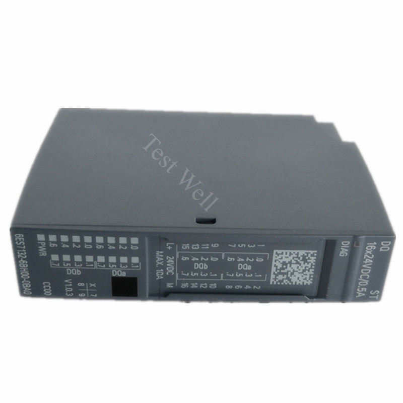
Siemens PLC consists of three core modules: CPU module, power supply module, and I/O & communication modules. The CPU executes logic programs, collects field sensor signals, and controls actuator operation; the power module provides stable DC power for the whole system; the communication module realizes data interaction with HMI, inverter, servo drive, and upper computer.
All Siemens PLC faults fall into three categories with clear logical boundaries:
[Internal Link Suggestion: Insert link to Original Siemens PLC Product Page (S7-1200/S7-1500/S7-300 Series)]
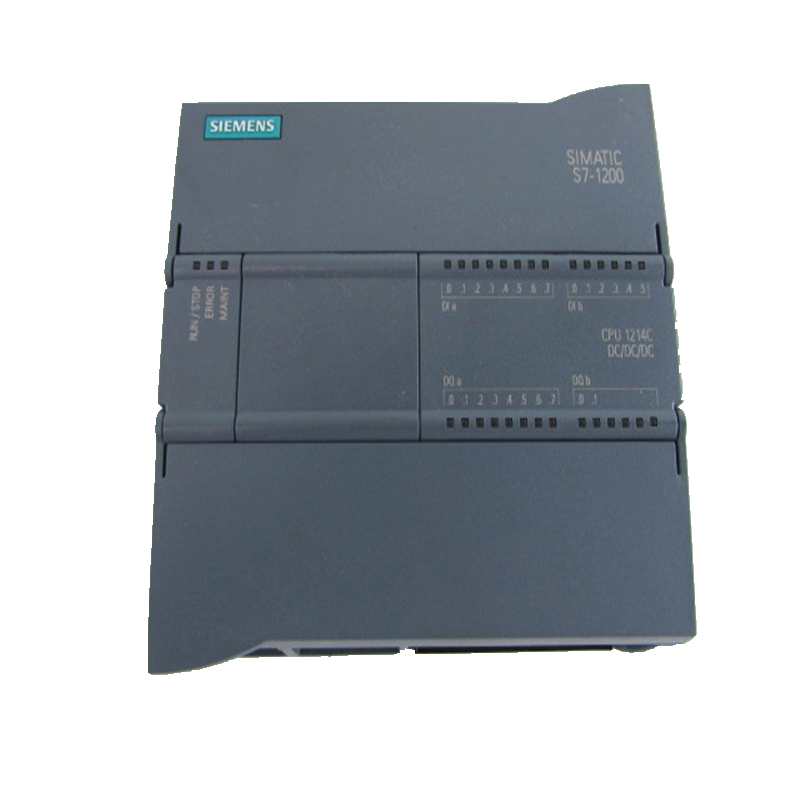
Without connecting to a computer for diagnosis, engineers can quickly locate faults through CPU panel indicator status, which is the most commonly used and efficient on-site troubleshooting method:
Combined with TIA Portal diagnostic buffer and on-site industrial high-frequency faults, we sort out the most common error codes, causes, and one-click solutions for mainstream Siemens PLC models:
3.1 CPU Startup & System Faults
Fault Phenomenon: PLC cannot start, SF light always on, RUN light off, system stops automatically
Main Causes: Damaged power supply module, loose backplane connection, program logic error, firmware crash, or incompatible module configuration
Repair Solution: Check and re-fasten power terminals and backplane; clear PLC diagnostic buffer; restore factory settings and re-download the verified complete program; update the latest official firmware to fix system bugs
3.2 Profinet/DP Communication Faults
Fault Code Performance: BF light alarm, upper computer cannot connect, slave devices offline, intermittent data loss
Main Causes: Broken or aging Ethernet/DP cables, missing terminal resistors, IP address conflict, incorrect station address, and firewall interception
Repair Solution: Inspect communication cables for damage and replace aging lines; confirm both ends of the DP bus are equipped with standard terminal resistors; re-modify unified IP addresses to avoid conflicts; turn off unnecessary firewall restrictions; re-download network configuration parameters
3.3 I/O Module Signal Abnormality
Fault Phenomenon: Input signal no response, output failure, random signal jumping, inaccurate data collection
Main Causes: Field sensor short circuit, overload burning I/O points, loose terminal wiring, strong electromagnetic interference, and module aging
Repair Solution: Disconnect field load to test empty I/O points; replace burned independent points or damaged I/O modules; reorganize signal cables and separate them from high-power power lines to reduce EMI interference; fasten all wiring terminals
3.4 PLC Battery & Data Loss Faults
Fault Phenomenon: BATT light alarm, program or parameter loss after power failure, system clock reset
Main Causes: Backup battery power exhaustion, long-term power-off storage, and aging battery module
Repair Solution: Replace the original Siemens PLC battery while the device is powered on to avoid data loss; back up all programs and parameters regularly; replace the battery every 1-2 years for long-term operating equipment
[Internal Link Suggestion: Insert link to Siemens PLC Spare Parts Page (Battery, I/O Module, Communication Cable)]
3.5 Overheating & Environmental Adaptation Faults
Fault Phenomenon: Intermittent system crash, random SF alarm, unstable operation in high-temperature environment
Main Causes: Dust accumulation inside the PLC cabinet, blocked heat dissipation holes, excessive ambient temperature, and humid environment causing circuit oxidation
Repair Solution: Clean PLC surface and internal dust regularly; ensure cabinet ventilation and heat dissipation; avoid long-term operation in ambient temperature above 40°C; place dehumidifiers in humid workshops to prevent circuit dampness
For on-site PLC faults, follow this standardized repair process to avoid blind disassembly and misoperation, improving repair efficiency:
Step 1: Fault Recording & Judgment Record indicator status, alarm codes, and fault occurrence time; distinguish hardware faults, communication faults, and program faults initially
Step 2: Power-off Inspection Cut off the power completely, check wiring looseness, cable damage, module burn marks, and dust accumulation
Step 3: Software Diagnosis Connect TIA Portal to view diagnostic buffer, locate specific fault points, and back up program data first
Step 4: Trial Repair & Reset Clear alarms, restart the PLC, update firmware, or reconfigure parameters for minor faults
Step 5: Parts Replacement & Verification Replace aging or damaged modules with original parts, re-download programs, and test full-load operation to confirm fault elimination
[Internal Link Suggestion: Insert link to Wholesale Original Siemens PLC & Accessories Page]
More than 80% of PLC sudden faults are caused by neglected daily maintenance. Scientific and standardized maintenance can effectively extend PLC service life and ensure long-term stable operation of automation systems.
5.1 Daily Inspection (Operator Routine Check)
5.2 Weekly Maintenance
5.3 Quarterly Maintenance
5.4 Annual Professional Maintenance
5.5 Long-Term Storage Maintenance
For idle Siemens PLC equipment, store it in a dry, dust-free, and corrosion-free environment. Power on and run the equipment for 20 minutes every month to prevent internal circuit dampness, parameter loss, and component aging.
On-site maintenance often confuses different fault types. The following intuitive distinction standards help accurate positioning:
PLC Hardware Fault Features
SF light is always on, the system cannot run normally, diagnostic buffer displays hardware abnormality, and the fault still exists after program reset and wiring inspection
Peripheral Equipment Fault Features
PLC runs normally without system alarms; signal abnormality is caused by sensor damage, actuator failure, or external circuit short circuit
Program & Configuration Fault Features
No hardware damage; equipment acts abnormally due to program logic errors, parameter mismatches, or incomplete configuration download