Mitsubishi PLC Troubleshooting: Common Error Codes, Repair & Maintenance Guide
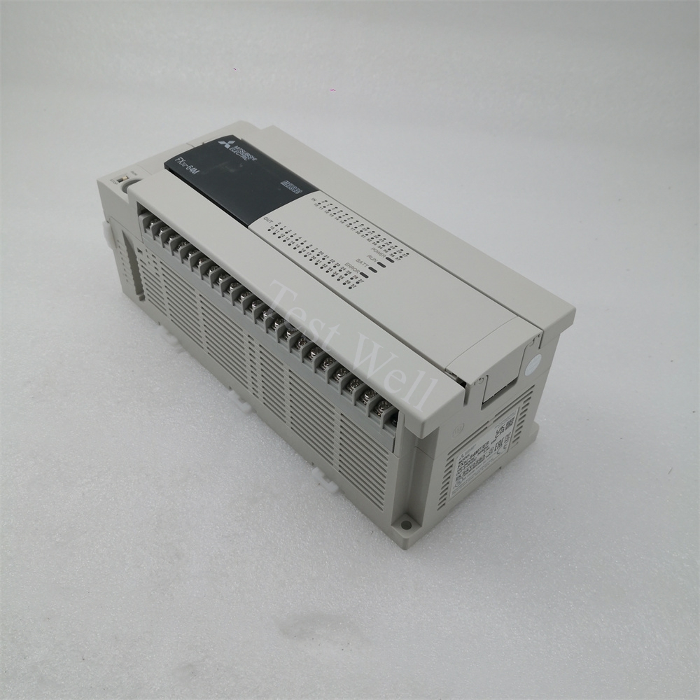
Mitsubishi MELSEC PLCs are globally recognized as mainstream industrial programmable logic controllers, widely deployed in packaging machinery, conveyor systems, CNC equipment, robotic production lines, and process automation systems. Classic series including FX3U, FX5U, and advanced iQ-R series are favored by global manufacturers for their stable performance, cost-effectiveness, flexible programming, and strong anti-interference capability.
During long-term continuous industrial operation, Mitsubishi PLCs frequently encounter typical faults such as ERR LED alarms, program execution failures, communication disconnection, I/O signal abnormalities, and memory data loss. Most unplanned production downtime is caused by misjudged LED status, unresolved error codes, irregular wiring, and insufficient daily maintenance, rather than inherent hardware defects. This professional SEO-friendly guide provides systematic fault classification, high-frequency error code troubleshooting, standardized repair procedures, and full-cycle preventive maintenance strategies to help global maintenance engineers quickly diagnose and fix Mitsubishi PLC failures.
A complete Mitsubishi PLC control system consists of three core parts: CPU main unit, power supply module, and expansion I/O & communication modules. The CPU executes user programs, collects field sensor signals, and controls on-site actuators; the built-in power supply provides stable DC power for the whole system; communication modules realize data interaction with HMI, inverters, servo drives, and upper computers via CC-Link, Modbus, and Ethernet protocols.
All Mitsubishi PLC industrial faults are divided into four core categories for precise and efficient troubleshooting:
[Internal Link Suggestion: Insert link to Original Mitsubishi PLC Full Series Product Page]
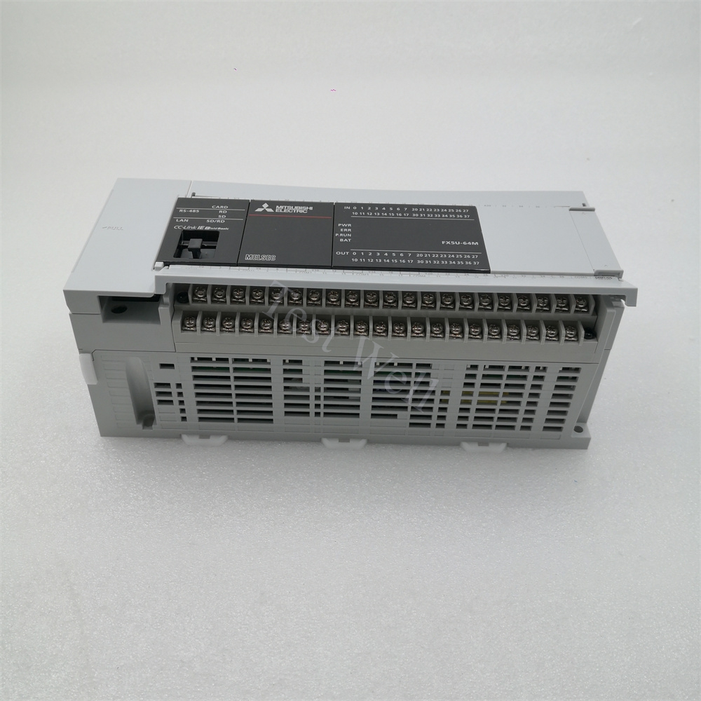
Mitsubishi PLCs adopt intuitive LED indicator status to help engineers complete preliminary fault positioning without computer connection, which is the most efficient on-site diagnosis method:
Combined with official Mitsubishi fault manuals and high-frequency on-site failures, we sort out the most common error codes stored in special registers D8060-D8067, root causes, and standardized repair solutions for FX and iQ-R series PLCs:
3.1 4000 Watchdog Timer Error (Core CPU Fault)
Fault Manifestations: ERR LED steady on, PLC stops running automatically, program execution interrupted
Core Causes: Infinite program loop, excessive program scanning time, severe electromagnetic interference, and CPU hardware aging
Repair Steps: Upload and check program logic to eliminate infinite loops and redundant commands; optimize program scanning cycle; strengthen PLC grounding to reduce EMI interference; restore system parameters and restart the device; replace the CPU module if the fault persists after software troubleshooting.
3.2 2220 CC-Link Communication Error
Fault Manifestations: COM LED abnormal, slave devices offline, intermittent data loss, equipment out-of-control
Core Causes: Loose or broken CC-Link cables, incorrect station number setting, missing terminal resistors, and field signal interference
Repair Steps: Inspect and re-fasten CC-Link communication cables; verify and correct device station addresses; install standard terminal resistors at both ends of the bus; isolate communication cables from high-power lines to avoid interference; re-download network configuration parameters.
3.3 6330 Modbus Communication Error
Fault Manifestations: Failed Modbus data transmission, no response from peripheral devices, irregular communication alarms
Core Causes: Mismatched baud rate and parity check, wrong slave address, damaged serial port circuit, and loose wiring
Repair Steps: Unify Modbus communication parameters (baud rate, data bit, parity check) between master and slave stations; check and correct slave address settings; inspect serial port wiring and replace damaged communication ports; restart the communication system for verification.
3.4 6340 Special Adapter Connection Error
Fault Manifestations: Expansion adapter unrecognized, module connection failure, system alarm
Core Causes: Loose adapter connection, incompatible expansion module model, and damaged adapter interface
Repair Steps: Power off and re-plug the special adapter and expansion modules; confirm module model compatibility with the main CPU; replace aging or damaged adapters and interfaces; re-identify hardware configuration via GX Works3.
3.5 0x4031 Address Out of Range Error
Fault Manifestations: HMI or upper computer fails to read data, system memory address alarm
Core Causes: Upper computer accesses undefined PLC memory address, unmatched HMI and PLC project files
Repair Steps: Cross-check HMI tag settings and PLC memory mapping; modify invalid access addresses; synchronize project files of upper computer and PLC; re-download configuration data.
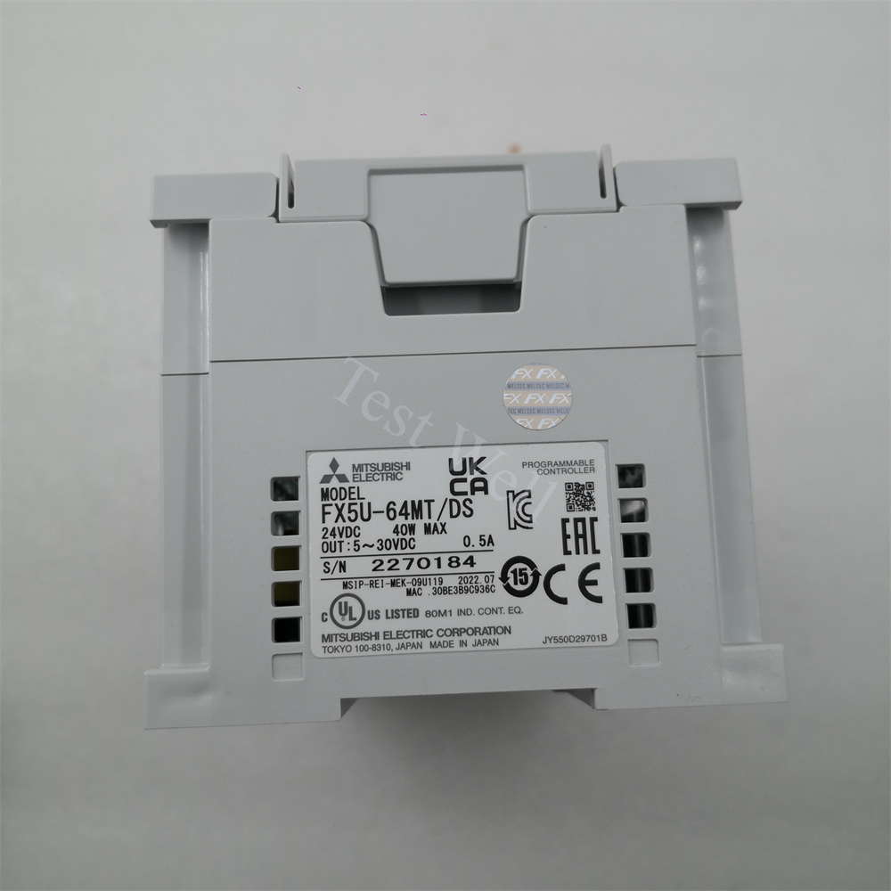
3.6 Battery & Memory Data Loss Fault
Fault Manifestations: BAT LED alarm, program/parameter loss after power off, system clock reset
Core Causes: Backup battery power exhaustion, long-term power-off storage, and aging memory module
Repair Steps: Replace the original Mitsubishi PLC battery in powered-on state to avoid data loss; back up programs and parameters regularly; replace the battery every 1-2 years for long-term operating equipment.
[Internal Link Suggestion: Insert link to Mitsubishi PLC Spare Parts (Battery, Adapter, Communication Module)]
Follow this standardized troubleshooting process to avoid blind disassembly and misoperation, greatly improving repair efficiency and reducing secondary equipment damage:
Step 1: Fault Recording & Preliminary Judgment Record LED status, error codes, and fault occurrence scenarios; initially distinguish CPU system, hardware, communication, and program faults.
Step 2: Power-Off Visual Inspection Cut off total power, check wiring looseness, cable damage, module burn marks, dust accumulation, and expansion connection firmness.
Step 3: Software Online Diagnosis Connect GX Works2/GX Works3 to read special register fault codes, view system diagnostic logs, and back up program data first.
Step 4: Trial Reset & Parameter Optimization Clear fault alarms, optimize program logic, correct configuration errors, and restart the PLC to eliminate minor system faults.
Step 5: Parts Replacement & Full Load Test Replace aging or damaged modules with original accessories, re-download programs and parameters, and perform no-load and full-load operation tests to confirm fault elimination.
[Internal Link Suggestion: Insert link to Wholesale Original Mitsubishi PLC & Accessories Page]
More than 80% of sudden Mitsubishi PLC faults are caused by neglected daily maintenance. Scientific and standardized maintenance can effectively extend PLC service life, stabilize system operation, and reduce industrial downtime.
5.1 Daily Routine Inspection
5.2 Weekly Maintenance
5.3 Quarterly Deep Maintenance
5.4 Annual Professional Maintenance
5.5 Long-Term Storage Maintenance
For idle Mitsubishi PLC equipment, store it in a dry, dust-free, and corrosion-free environment. Power on and run the equipment for 20 minutes every month to prevent internal circuit dampness, parameter loss, and component aging.
Accurate fault classification is the key to efficient maintenance. The core distinguishing features are as follows:
Mitsubishi PLC Hardware Fault Features
ERR/BAT LED keeps alarming, system cannot run normally, fixed error codes are displayed in diagnostic registers, and faults cannot be eliminated by program reset or wiring adjustment.
Peripheral Equipment Fault Features
PLC runs normally without system error codes; signal abnormalities are caused by damaged sensors, faulty actuators, or external circuit short circuits, irrelevant to the PLC body.
Program & Configuration Fault Features
No hardware damage exists; equipment abnormal actions and address errors are caused by program logic bugs, parameter mismatches, or incomplete configuration download.