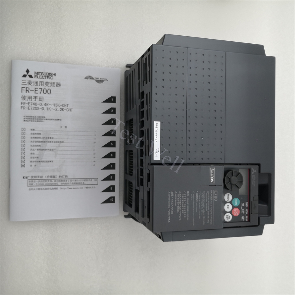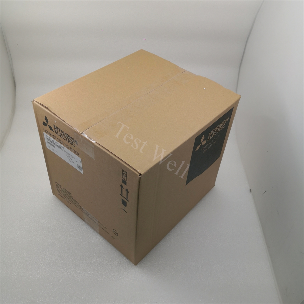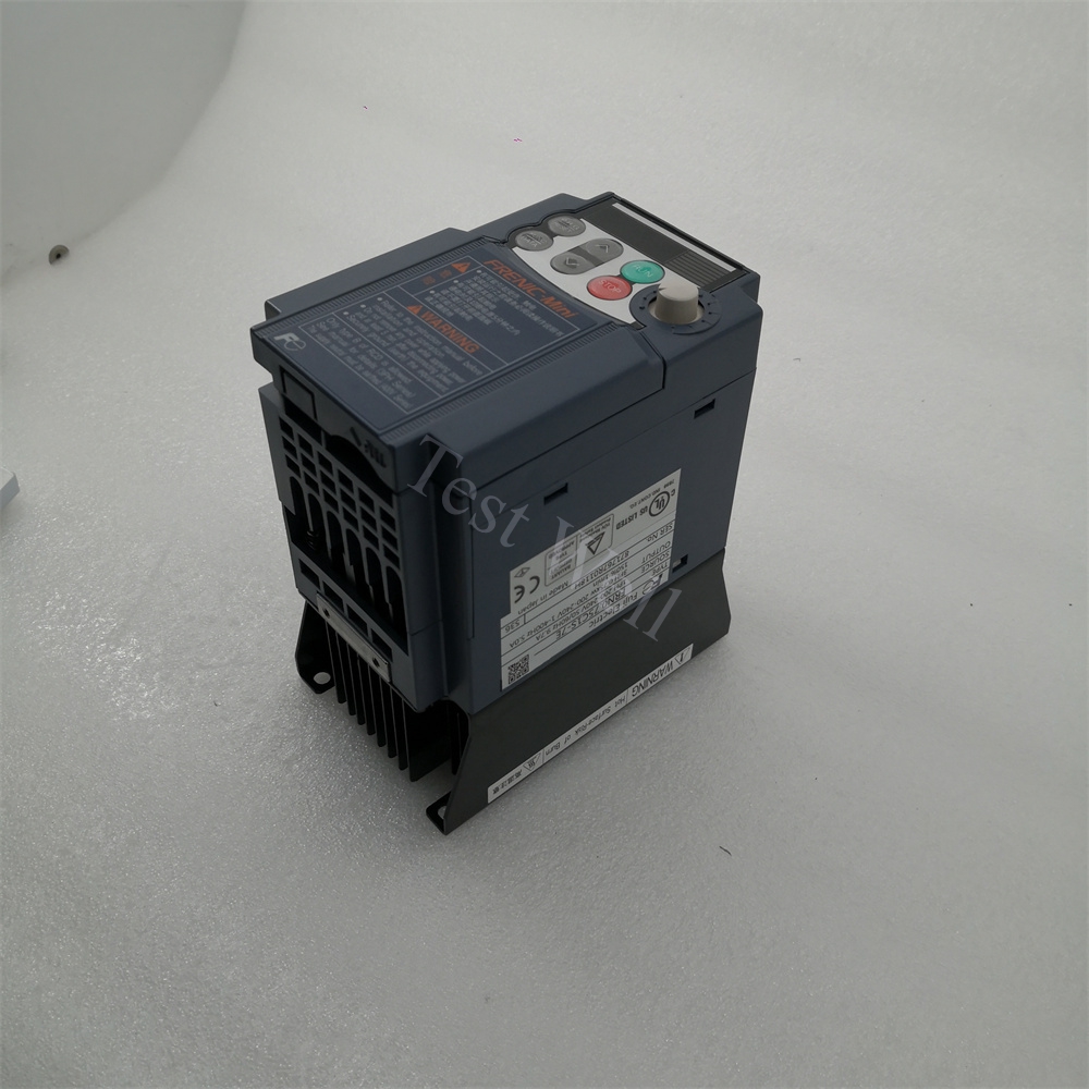
Mitsubishi Electric variable frequency drives cover four core industrial series widely deployed globally across packaging machinery, CNC machining centers, HVAC fan/pump systems, conveyor lines, cranes and process automation equipment: compact FR-D740, versatile FR-E800, energy-saving FR-F800, and high-torque heavy-duty FR-A800 series.
Please check our Mitsubishi Drive Product Page.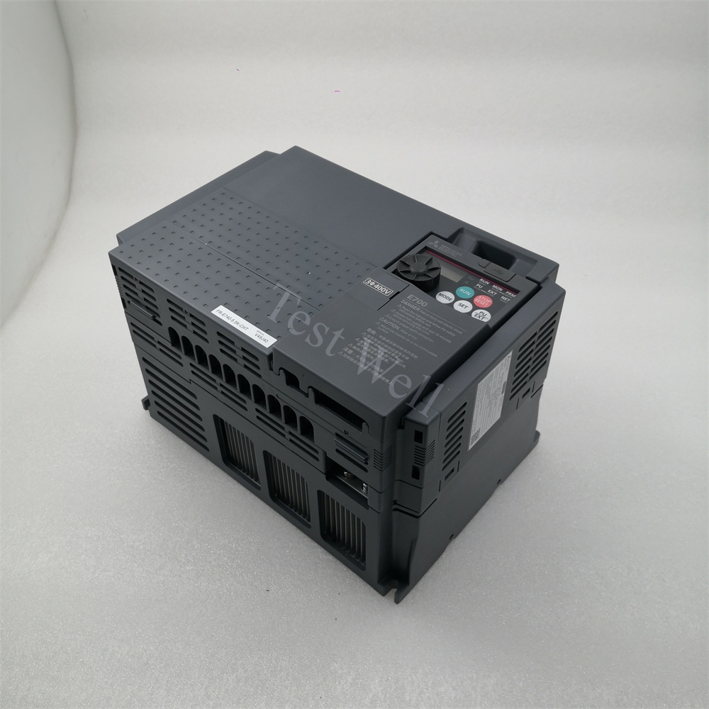
1. Core System Structure & Fault Classification of Mitsubishi VFD Drives
A complete Mitsubishi FR variable frequency drive consists of four core functional assemblies that control three-phase induction and permanent magnet motors:
Input Rectifier Stage: Converts AC mains power to stable DC voltage stored in DC bus capacitors; vulnerable to UV undervoltage and OrP input phase loss faults triggered by grid fluctuation, blown input fuses or loose R/S/T power terminalsMITSUBISHI ELECTRIC.
DC Bus Smoothing Capacitor Bank: Balances DC voltage ripple and absorbs motor regenerative braking energy; bulging, leaking capacitors repeatedly trigger E.OV overvoltage faults after 5–8 years of continuous operation.
IGBT Inverter Power Stage: Converts DC power to adjustable PWM AC for motor speed and torque control; short circuits and heavy overloads damage IGBT modules, causing E.OC series overcurrent and E.GF ground leakage protection trips.
Control & Cooling Assembly: Mainboard processes parameter configuration, Modbus communication and fault signal detection; built-in cooling fans and aluminum heat sinks prevent E.OH1/E.OH3 overtemperature protection shutdowns.
All Mitsubishi industrial drive faults fall into four clear categories for targeted troubleshooting:
Electrical Power & IGBT Faults: E.OC1/E.OC2/E.OC3 overcurrent, E.GF ground leakage, OrP input phase loss, E.OV1/E.OV2/E.OV3 DC overvoltage, UV undervoltage
Motor & Mechanical Load Faults: oL drive overload, EoL1/EoL2 electronic thermal relay trip, locked rotor, mismatched motor nameplate parameters, incomplete motor auto-tuning (Pr.96)
Communication & System Circuit Faults: CE1/CE2/CE3 Modbus RS485 communication timeout, parameter memory error, external interlock trip, EMI electromagnetic interference
2.Fast Preliminary Fault Diagnosis via Operating Symptoms & E-Series Fault CodesE.OC1/E.OC2/E.OC3/E.GF → Motor cable short circuit, ground leakage or damaged internal IGBT power module
Alarm pops during machine deceleration, E.OV1/E.OV2/E.OV3 displayed → Excessive regenerative energy without matched external braking resistor unit
Drive casing heats rapidly, continuous E.OH1 overtemperature warning → Clogged heat sink, seized cooling fan or cabinet ambient temperature over 40°C
Motor runs sluggishly with heavy vibration, frequent oL/EoL overload trips → Mechanical axis jamming or incorrectly set motor rated current Pr.09
No fixed fault code but unstable motor speed, random stalling → Poor cable shielding grounding, severe EMI interference or aging DC bus capacitors
PLC/HMI offline, Modbus communication lost, CE alarm displayed → Damaged RS485 cable, mismatched baud rate or duplicate slave station address.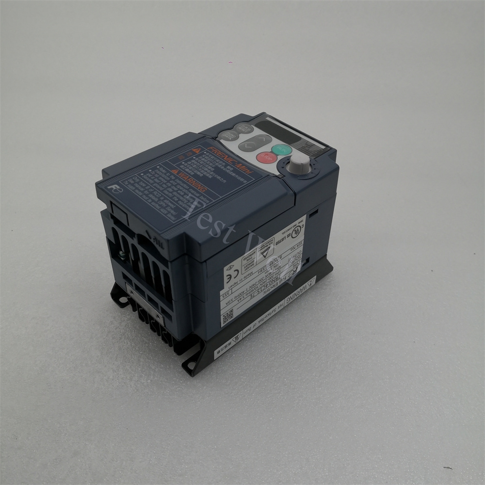
Combined with official Mitsubishi FR-A800/FR-E800 service manuals and high-frequency field workshop failure cases, we organize core fault codes, root causes and standardized operable repair steps for all mainstream drive series.
3.1 E.OC1 / E.OC2 / E.OC3 Overcurrent Fault
Fault Manifestations: Drive cuts output instantly during startup, steady operation or stopping; output current exceeds 200% of the drive rated protection threshold MITSUBISHI ELECTRIC.
Root Causes:
U/V/W motor output cable phase-to-phase short circuit or insulation breakdown to cabinet ground
Motor internal stator winding short circuit or locked rotor mechanical jam
Overly short acceleration time parameter Pr.01-10 and deceleration Pr.01-11 ramp settings
Damaged internal IGBT power modules or current detection Hall sensors on main circuit board
Excessively high carrier frequency Pr.72 in high-temperature cabinet environments
Repair Steps:
Perform full lockout-tagout (LOTO), cut main AC power and wait a minimum of 10 minutes for DC bus capacitors to fully discharge to avoid electric shock hazards.
Disconnect all U/V/W motor cables and run the drive in no-load test mode; if the E.OC fault disappears, the failure locates on motor or output wiring.
Test motor winding insulation resistance with a 500V megohmmeter; replace motors with insulation resistance below 1MΩ.
Extend acceleration Pr.01-10 and deceleration Pr.01-11 time values via the digital operation panel, lower carrier frequency Pr.72 for high-heat cabinets.
Inspect main circuit board for burnt discoloration; replace genuine Mitsubishi matching IGBT modules if hardware damage is confirmed.
Separate high-power motor cables and low-signal Modbus control cables with 30cm minimum spacing, install ferrite magnetic rings to suppress transient current interference.
3.2 E.OV1 / E.OV2 / E.OV3 DC Link Overvoltage Fault
Fault Manifestations: Overvoltage alarm activates during acceleration, constant speed or deceleration braking; DC bus voltage exceeds the internal safety threshold (800VDC for 400V-class drives)MITSUBISHI ELECTRIC.
Repair Steps:
Increase deceleration Pr.01-11 ramp time parameters to slow regenerative energy feedback speed during stop cycles.
Install genuine Mitsubishi matched braking resistor at designated P/+ and DB terminals for heavy inertial load equipment.
Add input line reactors or voltage stabilizers for factories suffering severe mains voltage surges.
Power off the drive and visually inspect DC bus capacitor banks for bulging casings, electrolyte leakage or discoloration; replace all aged capacitor sets entirely.
Reduce frequent rapid start-stop production cycles to cut repeated regenerative voltage surges on the DC circuit.