An axis that buzzes at certain speeds, hums after twenty minutes of running, or chatters only when the load is attached is one of the most frustrating faults in maintenance. Unlike a hard alarm that stops the machine and leaves a code on the display, intermittent servo motor vibration comes and goes, which means the evidence disappears before you can catch it. The pattern itself — when the vibration appears — is a powerful diagnostic clue, and in most cases it points to one of three families: mechanical, electrical, or tuning.
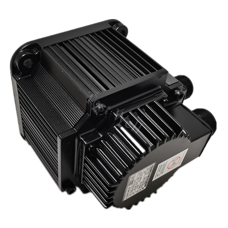
This guide walks through a field-proven diagnostic sequence used on Yaskawa, Mitsubishi, and Panasonic servo systems. Start with the hardware: most intermittent vibration is mechanical or electrical in origin, not a tuning problem. If you are troubleshooting a complete drive failure instead, browse our servo drive collection, or see our servo motor collection for replacement motors and spare parts.
Why Intermittent Vibration Needs a Different Approach
A continuously vibrating axis is easy to diagnose — the vibration is always there for your accelerometer or your hand. Intermittent vibration hides because it depends on operating state: speed, temperature, load, direction, or position. A gain that is marginally too high may be stable on a short move and unstable on a long one; a dried bearing is quiet when cold and audible once the grease warms; a shielding fault may only couple noise when a nearby VFD ramps up.
The fastest path to the root cause is to map the conditions under which vibration appears, then test each family of causes against that map. Resist the temptation to fix it by globally lowering gains first — that masks the symptom, slows the machine, and the vibration usually returns weeks later under different load.
Step 1 — Classify the Vibration Pattern
Run the machine through its normal cycle and note exactly when the vibration occurs. Match the pattern against this table:
| Pattern | Most Likely Cause Family |
|---|
| Only at certain speeds, in both directions | Mechanical resonance excited by the speed loop; notch filter mismatch |
| Only during acceleration or deceleration | Inertia ratio mismatch, position/velocity gain too high, loose coupling |
| Only at standstill after a move (hunting) | Position gain too high, backlash, or friction reversal (stick-slip) |
| Grows worse as machine warms up | Bearing wear, grease breakdown, thermal drift of clearances |
| Only when load is attached / direction reverses | Backlash, coupling wear, belt tension, or stiction in the drivetrain |
| Appears when nearby equipment runs | Electrical noise: encoder shielding, grounding, cable routing |
A slow-motion phone video (120–240 fps) captures the oscillation frequency and gives you a rough estimate to work with.
Step 2 — Rule Out Mechanical Causes
Inspect the drivetrain with the machine locked out before you open any parameter screen.
- Coupling and alignment. Check set screws and clamping hubs. A worn spider element or a loose clamping screw lets the rotor oscillate against the load — vibration that changes with direction reversal. Visible dial-indicator wobble of even a few hundredths of a millimetre at the coupling is enough to excite vibration.
- Backlash and belt tension. Rock the load by hand with the servo off; felt dead travel means backlash that causes standstill hunting. A loose timing belt whips and resonates; follow the manufacturer’s tension spec, not “tight as possible”.
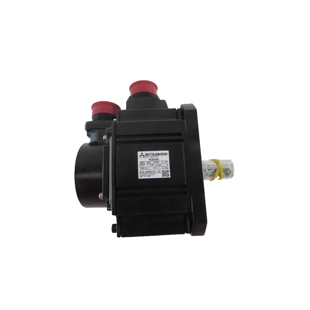
- Bearings. Rotate the shaft by hand (motor disconnected). Roughness or a notchy feeling indicates bearing damage — a classic source of vibration that worsens with temperature. If you are not equipped for encoder-safe bearing replacement, plan for a replacement motor such as the Mitsubishi HC-KFS43 or a Yaskawa equivalent.
- Mounting and structure. Torque-check motor flange bolts, gearbox bolts, and base anchors. A loose foot turns the whole motor into a resonant mass, and any rattling guard is a resonator that amplifies what the axis produces.
Step 3 — Check the Electrical Side
If the mechanical inspection is clean, the source may be noise corrupting the feedback signal.
- Encoder cable integrity. Wiggle-test the cable and connectors at both ends while watching position counts with the axis enabled. A fatigued conductor inside an intact-looking cable causes exactly these hard-to-repeat faults; on drag chains, inspect the fixed end where flex fatigue concentrates.
- Shielding and grounding. The encoder shield must be clamped 360 degrees to grounded metal at the drive end — not a pigtail screwed to a painted surface. Confirm the drive’s PE terminal and the motor frame share a low-impedance ground; paint or corrosion under a ground lug is enough to defeat it.
- Cable separation. Route motor power (U/V/W) and encoder cables separately — different ducts where possible, never bundled, crossings at 90 degrees. Motor power cable shields should be terminated at both ends per the drive manual.
- Shared noise sources. If vibration appears when a nearby VFD, welder, or large contactor operates, add ferrite cores on the encoder cable and reroute the offender.
- Insulation. With the motor disconnected, measure insulation resistance from each power lead to the frame at 500 V DC; a healthy motor reads in the megohm range.
Step 4 — Verify Load Inertia and Gain Tuning
Only after hardware checks pass should you open the tuning parameters, and the first value to confirm is the load-to-motor inertia ratio.
- Mitsubishi MR-J4. Read PB06 (load-to-motor inertia ratio); if it is far from the real value, auto tuning (PA08) computes gains the mechanics cannot support. The default speed loop gain PB09 is 823 rad/s — on a low-rigidity machine this must come down, not up. For resonance, set the machine resonance suppression filters: PB13 (filter 1 notch frequency, 10–4500 Hz) and PB14 (notch shape: depth 0 = −40 dB, 1 = −14 dB, 2 = −8 dB, 3 = −4 dB; width α = 2–5), repeated at PB15/PB16 for a second peak. For vibration that rings after the move, enable vibration suppression control 1 (PB19/PB20/PB21) — one-touch tuning can measure these for you.
- Yaskawa Sigma-series. Confirm Pn103 (moment of inertia ratio) matches reality; an inflated Pn103 is a leading cause of the vibration alarm described below. If the axis screams at a specific frequency, set the first-stage notch filter to it with Pn409 (50–5000 Hz, default 5000 = effectively disabled) and shape it with Pn40A (Q value) and Pn40B (depth). Pn460 lets the notch adjust automatically during autotuning — leave it enabled.
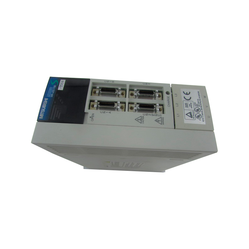
- Working order. Change one parameter at a time and re-run the exact motion pattern that reproduced the vibration, recording every change. For aging amplifiers where tuning no longer holds stable, replacing the drive (for example a Yaskawa SGDV-1R6A11A) is often more economical than chasing an intermittent internal fault.
Step 5 — Use the Drive’s Built-In Vibration Diagnostics
- Yaskawa. Alarm A.520 (Vibration Alarm) fires when the drive detects abnormal oscillation in motor speed; the manual directs you to reduce motor speed or the speed loop gain (Pn100), correct the inertia ratio (Pn103), and review the vibration detection level (Pn312 or Pn384). Parameter Pn310 chooses whether the same condition reports as the A.520 alarm or only the A.911 warning — treat intermittent A.911 warnings as early vibration alarms, not nuisance. Alarm A.521 (Autotuning Alarm) means vibration was detected during custom tuning, Easy FFT, or the tuning-less function; use SigmaWin’s FFT analysis to capture the resonance spectrum before changing filters.
- Mitsubishi MR-J4. There is no dedicated vibration alarm; escalating oscillation usually surfaces indirectly as AL.52 (Error excessive) or AL.31 (Overspeed). Use MR Configurator2’s machine analyzer to identify resonance peaks, then apply the PB13/PB15 notches and re-tune with one-touch tuning.
Repair or Replace: Making the Call
- Replace the motor when bearings are rough, insulation is marginal, or the encoder intermittently drops counts.
- Replace the amplifier when vibration correlates with drive temperature or the same alarm returns across different motors.
- Replace cables at the first sign of shield or conductor fatigue — they are inexpensive compared to a second breakdown.
Preventive Maintenance Schedule
- Monthly: inspect coupling set screws, belt tension, and mounting bolts; listen to each axis at cycle start.
- Quarterly: check encoder cable strain relief and drag-chain sections for flex fatigue; verify shield clamps are tight and conductive.
- Annually: record inertia ratio and key gains per axis as a baseline and trend drift; shrinking stability margin is early evidence of mechanical wear.
- On every service: back up drive parameters after any successful tuning change.
FAQ
Q: Can I just lower the gains until vibration stops?
You can, but you are treating the symptom. If vibration is mechanical, gains keep drifting down until the machine is sluggish and the fault returns. Fix the hardware first, then re-tune to recover performance.
Q: What does the Yaskawa A.520 alarm actually mean?
It means the Sigma-series drive measured abnormal oscillation in motor speed. Check speed/torque waveforms, then per the manual reduce motor speed or Pn100, verify Pn103, and check the vibration detection level (Pn312/Pn384).
Intermittent servo vibration rewards a structured approach: classify the pattern, eliminate mechanical and electrical causes, verify the inertia ratio, then use the drive’s own analysis tools. If diagnostics point at a failing motor or amplifier, you will find priced, tested replacement units — including the Mitsubishi MR-J2S-40A and the Yaskawa SGDV series — in our servo drive collection.


