Yaskawa’s GA800 general-purpose drive and E1000 HVAC drive share one 1000-series protection architecture: a threshold is crossed, the output is cut, the fault relay changes state, and a short code blinks on the keypad. The codes look nearly identical, yet the two families do not diagnose the same way. The E1000 adds HVAC process protections a GA800 never shows (UL3, UL6, FbH, FbL); the GA800 adds drive-level diagnostics the E1000 does not use (SC, oS, dEv, rH). Reading the code, then the trace behind it, separates a ten-minute fix from an unnecessary replacement.
Replacement power stages and drives are listed in our industrial inverter collection.
Each trip is stored twice: the U2 monitor group holds the operating point at the instant of the fault, and U3 keeps the last several faults with cumulative run time. An oC at 2 Hz and 400 % current is a jammed load; the same oC at 48 Hz with current climbing slowly is a tuning or V/f problem. Photograph both screens first — a reset wipes the evidence.
Fault manifestations. oC trips when output current exceeds the overcurrent detection level. GF reports a ground fault on the output side, usually at power-up before the run command. SC (GA800) means a short circuit or IGBT failure — oC at every start with the motor disconnected is usually SC-level damage.
Root causes. Shorted or grounded motor cable, winding insulation breakdown, a jammed load, acceleration time shorter than the inertia allows, torque compensation (C4-01) too high, or a failed power module.
Repair steps. Lock out, wait for the charge lamp to go out, then megger motor and cable separately — anything below 1 MΩ to ground must be repaired first. Run the drive into a test motor; if oC or SC returns unloaded, the output stage is damaged and the module set must be replaced — our IGBT and power module collection lists common footprints. Otherwise lengthen C1-01/C1-03, enable speed search (b3-01 = 1) and correct the V/f pattern.

Fault manifestations. oL1 is the electronic thermal protector for the motor; oL2 is the drive’s own overload protection. Both accumulate over minutes rather than tripping instantly.
Root causes. oL1: E2-01 (motor rated current) left at default after a motor swap, L1-01 set for the wrong motor type, or real mechanical overload. oL2: drive undersized for the duty cycle, accel/decel times too aggressive, continuous low-speed running at high carrier frequency (C6-02), or an input phase loss.
Repair steps. Clamp all three output phases under load and compare with nameplate FLA. Enter the real current in E2-01, match L1-01 to the motor type, and raise C1-01 to C1-08 before considering a larger drive. If current is balanced but trips continue, review C6-02.
Fault manifestations. oH is a heatsink overheat fault referenced to L8-02; oH1 is the higher-temperature variant; oH2 is a drive overheat pre-alarm configured by L8-03; oH3/oH4 come from a motor PTC input; FAn signals a stopped internal fan.
Root causes. Clogged heatsink fins, a slow or failed fan, ambient above rating, drives mounted without side clearance, or a PTC curve that no longer matches L1-03/L1-04.
Repair steps. With power off, vacuum the heatsink from the bottom up and check the fan spins freely; replace any fan that stalls, squeals or draws high current. Confirm L8-02 suits the panel, measure ambient at the inlet, and check thermistor resistance cold and hot before replacing a motor on oH3/oH4.
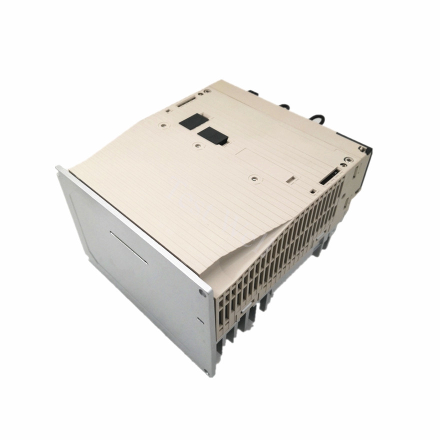
Fault manifestations. ov trips above roughly 410 VDC on 200 V class or roughly 820 VDC on 400 V class (740 VDC when E1-01 is set below 400 V). It appears most often during deceleration or when a high-inertia fan coasts.
Root causes. Deceleration shorter than the regenerated energy allows, no braking resistor or unit, L3-04 stall prevention disabled, or a supply tap pushing incoming voltage near the upper limit.
Repair steps. Lengthen C1-02/C1-04/C1-06/C1-08 first — this solves most fan and pump cases. If the load genuinely regenerates (cranes, downhill conveyors, extruders), fit a braking resistor or unit, set L3-04 = 1, and wire the resistor’s thermal switch so the fix does not become an rH trip.
Fault manifestations. Uv1 is main-circuit undervoltage: bus below the L2-05 setting, about 190 VDC on 200 V class (160 VDC single-phase) and 380 VDC on 400 V class (350 VDC when E1-01 < 400 V). Uv2 is a control supply dip; Uv3 is a soft-charge answerback fault — the pre-charge contactor did not confirm closed.
Root causes. Blown input fuse or tripped breaker on one phase, loose terminal screws, supply sag when a large load starts, ageing main capacitors, or a pitted soft-charge contactor.
Repair steps. Measure all three input phases line-to-line and line-to-neutral; a 15–20 V imbalance under load is a supply problem, not a drive problem. Check U4-05 capacitor maintenance — past 90 %, plan replacement rather than chasing resets. For Uv3, inspect the contactor coil and auxiliary contact.
Fault manifestations. PF is input phase loss (L8-05), LF output phase loss (L8-07), and LF2 output current imbalance, most often on PM motors.
Root causes. Blown input fuse, single-phasing upstream, a loose motor terminal, or one leg of the power module not switching.
Repair steps. Verify fuses with a meter, then torque every main-circuit terminal. For LF, disconnect the motor and measure resistance across U-V, V-W and W-U; a large deviation points to cable or winding. A healthy motor with LF persisting means the SC repair path applies.
Fault manifestations. bUS is an option-card communications error, CE a MEMOBUS/Modbus communication error, CALL a serial transmission error, and oFA an option card fault or a card that does not match the drive.
Root causes. Terminating resistor missing or doubled, shield grounded at both ends, wrong baud rate or station address, or a card seated unevenly after maintenance.
Repair steps. Reseat the card with power off, confirm the model matches the slot, then check network parameters against the master. Ground the shield at one end, keep signal and motor cables 200 mm apart, and fit the terminating resistor only at the trunk ends.
Fault manifestations. CPF00/CPF01 are control circuit errors, CPF03 control board connection, CPF06 EEPROM data, CPF07/CPF08 terminal board connection, CPF24 drive unit signal, and CPF26–CPF34 further control circuit faults. Err is an EEPROM write error, oPr a keypad connection fault, CrST a refused reset.
Root causes. Loose ribbon cable between control and terminal boards, condensation, EMI from welding equipment, or board failure after a surge.
Repair steps. Power down, wait for the charge lamp, reseat every internal connector, dry condensation with clean air, then reapply power. If CPF06 or Err persists, back up parameters first — a corrupted EEPROM may need a factory reset that erases the application settings.

UL3 (undertorque) and UL6 (motor underload) trip when output current stays below L6-02 for longer than L6-03 — factory settings are 15 % of rated current for 10.0 s. L6-01 selects detection at speed agree or whenever the run command is active, and an alarm (settings 5 and 6) or a fault (7 and 8); UL6 uses settings 9–12 with the L6-13 underload curve.
FbH (excessive PI feedback) and FbL (PI feedback loss) come from the HVAC loop: with b5-12 = 2 or 5, feedback above b5-36 for longer than b5-37 triggers FbH, while feedback below b5-13 for longer than b5-14 triggers FbL. Both point at a failed static pressure sensor, a blocked impulse line, or a belt that has slipped off.
Four parts limit the life of these drives: cooling fan, DC bus capacitors, soft-charge bypass relay and IGBTs. The E1000 exposes all four as LT-1 to LT-4 counters plus TrPC for IGBT life at 90 % — log them at every service visit. Clean heatsinks and cabinet filters on a fixed interval, torque main-circuit terminals annually, and keep panel ambient inside the drive rating. Record every code with its U2 trace — a chronic oL2 reset each shift is a design problem, not a maintenance routine.
Can I reset a fault and keep running? Only after recording the U2 trace. Repeated resets on oC, SC or GF risk destroying the power module, and L5-07 can restrict who may reset.
Is a GA800 a drop-in replacement for an E1000? No. The E1000 has HVAC-specific underload and PI supervision the GA800 does not provide.
Where do I find replacement modules? Start with the inverter collection or the IGBT module collection; for machines running both families we stock Yaskawa amplifiers such as the SGDV-1R6A11A and SGDH-01AE-OY.


