The Fanuc Series 0i-D and 30i controllers run a large share of the world’s machining centres and lathes, and both report faults through the same alarm-grouping scheme: a letter prefix that names the system area, followed by a 3- or 4-digit number. This article covers the CNC system-level groups — PS, SV, OT, IO and APC — rather than the amplifier or encoder hardware faults already written up separately on this site.
When one of these alarms appears, the message on the screen is only the headline; the diagnostic bits behind it are what decide the fix. Most service calls we handle are resolved by reading the alarm number correctly and opening the diagnostic screen before touching hardware. This guide covers the alarm structure, the codes technicians actually meet, and a step-by-step path for each group, checked against the Fanuc 0i-D/30i Alarm Manual (B-64303EN series).
Please check our industrial modules and encoder range — Fanuc encoders such as the A860-2000-x021 are among the spares we stock — if you are sourcing a replacement rather than repairing.
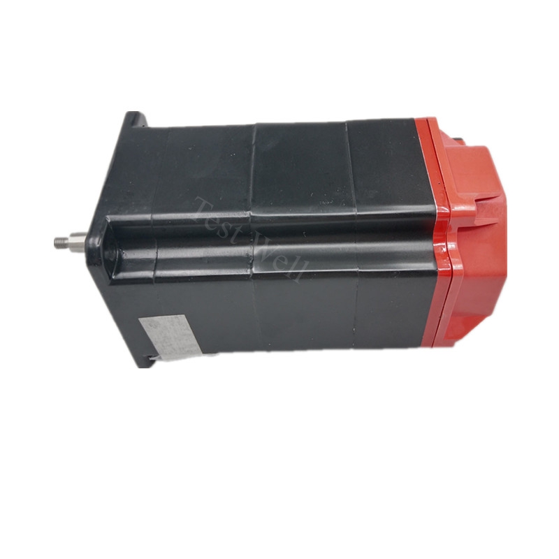
Every alarm follows the same shape: a group prefix and a number.

Fault Manifestations. PS0001 points at the power supply side of the CNC — the 24 V or the internal supply has flagged a fault, and the control may not finish its boot or drops out mid-cycle.
Root Causes. A dropped 24 V supply at the cabinet, a failing power supply unit, a short on the regulated side, or a parameter write that needs a power cycle (the PS0000/PS0100 family) left unprocessed.
Repair Steps. Measure the 24 V at the CNC and the I/O deck, confirm the supply can hold load, and cycle power after any parameter change that asks for it. If the supply drops under load, replace the power supply unit before chasing axis faults.
Fault Manifestations. PS0530 is the battery-class alarm: the absolute pulse encoder backup battery has fallen below the threshold, so absolute position data is at risk.
Root Causes. An exhausted encoder backup battery, a battery left disconnected during a board change, or a cable break feeding the encoder battery line.
Repair Steps. Replace the battery with power held on (never with the control off, or you lose the absolute reference), then re-establish the zero-point reference. Log battery age — most shops replace at the scheduled interval rather than waiting for the alarm.
Fault Manifestations. SV0430 is servo motor overheat (the encoder thermo element tripped). SV0431 is inverter/amp circuit overload, SV0433 is DC-link voltage low, SV0438 is inverter current abnormal, and SV0441 is abnormal current offset detected in the current-sense circuit.
Root Causes. Overload or blocked cooling (SV0430/SV0431), a sagging or missing 24 V / DC-link supply (SV0433), a shorted or grounded motor cable, a faulty amplifier, or a damaged current-sense channel (SV0438/SV0441).
Repair Steps. Read diagnostic No. 308 (motor temperature) and No. 352 to see whether the heat is real. For SV0433, measure the strong-voltage input and the DC-link wiring. For SV0438/SV0441, megger the motor and cable, swap the feedback lead, then replace the servo amplifier if the offset persists. The Fanuc A860-0203-T015 encoder covers many of the feedback replacements behind these alarms.
Fault Manifestations. SV1026 (and the related SV106x axis/FSSB configuration group) appears when the axis-to-amplifier assignment in the parameters does not match the physical FSSB connection.
Root Causes. A changed axis parameter, an amplifier added or removed without re-configuring FSSB, a fibre or cable mismatch, or a control board swapped without reloading the configuration.
Repair Steps. Open the FSSB configuration screen, confirm the detected amplifiers match the parameter set, correct the axis assignment, and re-run FSSB coupling. Reload the saved parameter set if the configuration was lost during a board change.
Fault Manifestations. OT0500/OT0501 are positive/negative soft-limit (stored stroke check 1) exceeded. OT0502–OT0505 are the further soft-limit bands; OT0506/OT0507 are the positive/negative hard-limit switches; OT0508/OT0509 are turret interference; OT0510/OT0511 (and up to OT0520) are travel pre-check alarms raised before movement begins. OT0670 sits in the same overtravel group as a further stroke-limit condition.
Root Causes. Jog or program coordinates beyond the allowed travel, a reference return not completed, a limit-switch trip, a travel-limit parameter mismatch, or a programmed endpoint inside a prohibited zone.
Repair Steps. For a soft limit, jog back inside the travel range and reset. For a hard limit, hold the overtravel release, clear the switch, and jog off. For pre-check alarms, correct the program endpoint. Always confirm the reference position is valid before resuming automatic mode.
Fault Manifestations. IO086/IO087 are reader/punch (external I/O) interface alarms — the prepare signal dropped or the input would not stop. IO090 appears when the machine is too close to the reference point or the return speed is too low to complete zero return; IO091 appears when a manual reference return is attempted while auto operation is paused with residual motion.
Root Causes. A disconnected or mis-set I/O device, a baud-rate/format mismatch on the external interface, or an incomplete or conflicting reference-return condition.
Repair Steps. For IO086/IO087, check the external I/O device power and handshake signals and match the communication settings. For IO090/IO091, move the axis clear of the reference point, ensure the return speed meets the parameter, and finish the reference return before any manual zero-return attempt.
Fault Manifestations. The APC 3nn group covers absolute pulse encoder faults — most commonly APC0300 (reference return required, absolute position lost) and APC0301 (APC communication error).
Root Causes. A battery event that dropped the absolute reference, a broken encoder cable, a contaminated connector, or a faulty pulse coder.
Repair Steps. After a battery change or power loss, perform the zero-return / referencing procedure. For APC0301, inspect the encoder cable and battery line, then replace the encoder if communication does not recover. Because the APC alarms and PS0530 share the same battery root cause, fix the battery path first.
| Interval | Task | Prevents |
|---|---|---|
| Quarterly | Check cabinet 24 V and cooling fans | PS0001, SV0430, SV0431 |
| Every 6–12 months | Verify travel-limit and reference parameters | OT0500–OT0520 |
| On schedule | Replace absolute encoder batteries under power | PS0530, APC 3nn |
| After any board change | Reload and verify FSSB configuration | SV1026, IO alarms |
What is the difference between PS0530 and an APC 3nn alarm?
They share a root cause — the absolute encoder battery — but at different layers. PS0530 is the CNC power/parameter-level battery alarm; APC 3nn is the encoder-side absolute-pulse-coder alarm (lost reference or comms). Fix the battery path and re-reference for both.
Why does SV0430 appear when the motor is not actually hot?
Read diagnostic No. 308. If the displayed temperature is high but the motor is cool, the temperature-detection circuit or encoder is faulty, not the motor — replace the encoder or its feedback path rather than derating the cut.
How do I clear an OT0506 hard-limit alarm safely?
Hold the overtravel release, confirm the limit switch has physically cleared, jog the axis back inside travel, then release. Do not force a reset while the switch is still made, or you risk driving further into the stop.
Browse our industrial modules and encoder range for Fanuc servo amplifiers, pulse coders and absolute encoders.


