By Jennifer Zhang
The PowerFlex 4 family — the PowerFlex 4 (22A), PowerFlex 4M (22F), PowerFlex 40 (22B) and PowerFlex 400 (20BC) — is still one of the most widely installed compact drive families in older plants. These drives rarely die suddenly; they announce a problem through an F-code on the integral LED display first. Reading that code correctly is the difference between a five-minute fix and a wasted replacement. This guide walks through the fault codes these legacy drives actually throw in the field, their root causes, and the repair steps that get production moving again. Looking for a replacement compact VFD? Browse our inverter collection for in-stock units.
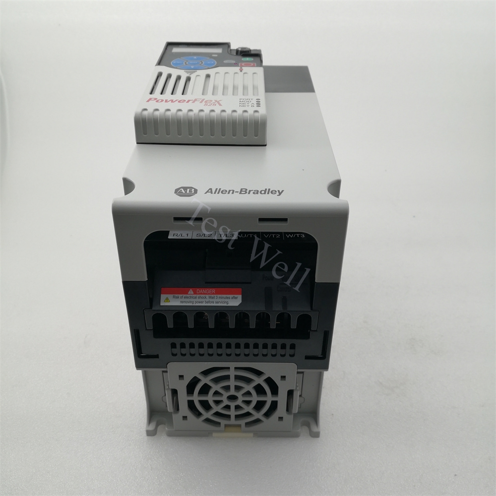
The catalog number tells you which manual to reach for: 22A is PowerFlex 4, 22F is PowerFlex 4M, 22B is PowerFlex 40 and 20BC is PowerFlex 400. The first three display base faults as three-digit codes (F002, F003…), while the PowerFlex 400 displays the same faults as F2, F3 and so on — identical meanings, different format.
To clear most faults: press the Stop key, cycle power, or use the fault-clear parameter (A100 [Fault Clear] on the PowerFlex 400). Codes marked as auto-reset/run type in the manual can clear automatically through parameters A092 [Auto Restart Tries] and A093 [Auto Restart Delay] — useful for transient input-power dips, but never a substitute for fixing the cause.
Fault manifestations: The drive trips when the run command is issued, or repeatedly during operation. The auxiliary input interlock — an external trip contact wired to the drive — has opened.
Root causes: An e-stop loop or external overload relay opened; wiring at the auxiliary terminals (31 and 32 on the PowerFlex 4/40) is loose; or a drive was commissioned without an auxiliary device but the terminal jumper is missing or corroded.
Repair steps: Meter the interlock circuit while the fault is active. If the external device is genuinely tripping, fix that device first. If the drive runs without any auxiliary device, confirm the jumper is seated, or configure the affected digital input as Not Used so the drive stops watching an empty terminal.
These three codes are all DC-bus voltage problems, and they account for a large share of nuisance trips on aging drives.
F003/F3 Power Loss: the DC bus dropped below the run threshold during operation. Check for input phase loss, loose mains terminals (torque them — thermal cycling loosens them over years), and upstream fuses or contactors with a failing pole.
F004/F4 Undervoltage: the incoming AC line fell below roughly 85% of nominal. Measure the supply during the trip window — plant voltage sags from large motor starts are the usual culprit. On a drive that repeatedly trips F004 with a healthy supply, the DC bus electrolytic capacitors are probably worn out; that is a straightforward, economical bench repair.
F005/F5 Overvoltage: the DC bus climbed above its ceiling — around 405 VDC on the 230 V class or 810 VDC on the 460 V class. Causes: a deceleration ramp too short for the load inertia, an overhauling load, or incoming line transients. Lengthen the decel time first; if the load must stop faster, add or verify a dynamic brake resistor or chopper.
F006 Motor Stalled: the drive cannot accelerate the load within the stall time. Look for a mechanical jam, a locked brake, or motor parameters that no longer match the connected motor after a swap. Raising the stall time only helps if the load is genuinely heavy but healthy.
F007 Motor Overload: the electronic thermal overload tripped on sustained overcurrent. Verify the motor nameplate data is actually entered in the drive parameters (a surprisingly common commissioning error), measure running current against it, and inspect the driven machine for binding bearings or a loaded process. Repeated F007 with correct settings means the motor or load is genuinely undersized — not a drive fault.
Fault manifestations: Trip during heavy duty cycles or hot weather; often returns within minutes of a restart.
Root causes: Blocked or dirty heatsink fins, a failed cooling fan, or ambient temperature beyond limits — 40°C for IP30/NEMA 1 installations, 50°C for open-type mounting. A PWM frequency set unnecessarily high also adds heat.
Repair steps: Blow the fins out with low-pressure compressed air, confirm the fan spins freely, check cabinet ventilation and filters, and drop the carrier frequency from 8 kHz to 4 kHz where acoustics allow. If the drive trips on heatsink temperature while stone cold, the thermistor or control board is at fault.
Treat these as motor-and-cable problems until proven otherwise.
F012 Hardware Overcurrent: output current exceeded the fast hardware trip level (typically above 200% of drive rating, essentially instantaneous). Disconnect the motor and megger the cable and windings; check for a phase-to-phase short in the motor junction box. If both are healthy, the output IGBT bridge has likely failed and the drive needs replacement.
F013 Ground Fault: the sum of the three-phase output currents exceeded the ground-fault threshold (roughly 50% of drive rating). Insulation breakdown in the motor cable, moisture in the motor terminal box, or failing windings. Megger phase-to-ground at 1000 V (expect well above 10 MΩ), open and dry the terminal box, and replace damaged cable before restarting. For a dependable swap unit, the 22B-D010N104 PowerFlex 40 drive (480 V class, 10 A, 5 HP) is a top-ordered replacement for this failure pattern.
The PowerFlex 400 reports per-phase detail: F38/F39/F40 are phase U, V or W to ground; F41/F42/F43 are UV, UW or VW phase shorts. The check sequence matches F013/F012, but the codes tell you which phase to meter first. After clearing wiring and motor faults, if the drive still reports a phase short with the motor leads completely disconnected, the output stage is damaged — replace the drive.
F033 Auto Restart Tries: the drive exhausted its automatic restart attempts, usually chasing a persistent F005 or F012. Read the fault history to find what kept tripping it; auto-restart is symptom management, not a fix.
F048 Params Defaulted: the drive was commanded to write defaults to EEPROM. Clear the fault, cycle power and reprogram; if it appears spontaneously, suspect a brown-out during a parameter save.
F063 SW OverCurrent: the programmed software current trip level was exceeded — check the load and the trip setting before assuming an electrical fault. F064 Drive Overload: output current exceeded the drive’s overload envelope; reduce load or extend the acceleration time.
F070 Power Unit: a failure was detected in the power section. Cycle power; if it returns, the drive is done. F071 Net Loss and F081 Comm Loss: the network or the RS-485 (DSI) port stopped communicating — check cabling, termination, adapter seating and timeout settings (C105 [Comm Loss Action] on the 400 controls the response if an adapter is intentionally removed). F094 Function Loss (PowerFlex 400): the start source is set to setting 6 and the input at terminal 01 opened — close the input and restart. Larger 400 frames such as the 20BC015A0AYNANC0 (15 A fan/pump-rated unit) most often reach the bench for F070 after years on a hot wall — power-stage failures, not control problems.
F100 Parameter Checksum: the stored parameter checksum no longer matches. Reset to defaults (P041 [Reset To Defaults] on the 400), reload your saved parameter file, and reconfigure. If F100 returns after a clean reset, the NVRAM is failing and the drive should be retired. F122 I/O Board Fail: a control/I-O hardware failure — cycle power once; if it persists, replace the drive. A known-good replacement such as the 22B-D2P3N104 (240 V class, 2.3 A) is the fastest route back to production for small-frame panels.
Q: Can I clear F012 or F013 and keep running?
A: Only after the motor and cable test clean. Clearing without testing risks welding the output stage.
Q: Is an F005 overvoltage fault caused by the utility?
A: Usually not. Regeneration from a fast-decelerating load is the most common cause — lengthen the decel time or add a braking resistor first.
Q: Which fault codes mean the drive itself is dead?
A: F070, F122, and F100 that returns after a reset point at internal hardware. F012/F013/F038–F043 that persist with the motor disconnected point at the output stage.
Q: Are parts still available for these legacy drives?
A: Yes. The 4/4M/40/400 lines are discontinued but heavily traded; tested units for most frames remain in stock — check our inverter collection for availability.


