By Jennifer Zhang | Test Well Electronics Limited
The Yaskawa A1000 series is a high-performance vector-control inverter widely deployed in CNC machines, conveyors, pumps, and HVAC systems. When a fault code flashes on the keypad, production stops and every minute of downtime costs money. This guide gives field technicians a practical, code-by-code breakdown of the most common A1000 faults—what they mean, why they happen, and how to fix them safely.
If you are looking for replacement drives or spare servo motors, browse our inverter collection or check the Yaskawa SGME–04ADA61 servo motor and the SGD7S–470A20A servo drive for compatible upgrade paths.
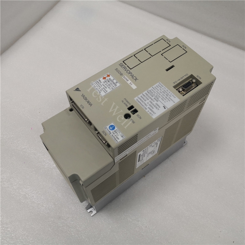
1. Overvoltage — ov (Fault Code ov)
Fault Manifestation
The DC bus voltage exceeds the threshold (roughly 410 V on a 400 V class unit). The drive trips and the motor coasts to a stop.
Root Causes
- Regenerative energy from a high-inertia load during deceleration.
- Input line voltage is higher than nominal (utility spike or improper tap setting).
- Braking resistor is open, undersized, or not connected.
- The deceleration time (C1–02) is set too aggressively.
Step-by-Step Repair
- Measure incoming AC with a true-RMS meter; verify it is within ±10 % of the drive nameplate rating.
- Inspect the braking resistor terminals (+3 and B1/B2). Look for burnt smell, discoloration, or loose crimps.
- If the load is high inertia, lengthen C1–02 in 0.5 s increments or add an external braking unit.
- Enable Stall Prevention during deceleration (L3–04 = 1) as a temporary workaround while you source parts.
2. Overcurrent — oc (Fault Code oC)
Fault Manifestation
Output current exceeds roughly 200 % of the drive rating. The IGBT module shuts down instantly to protect itself.
Root Causes
- Phase-to-phase or phase-to-ground short at the motor terminals or inside the motor windings.
- Damaged IGBT output module (often preceded by a previous short-circuit event).
- Incorrect motor parameter auto-tuning; the current model is fighting the real load.
- Mechanical jam or seized bearing causing locked-rotor current.
Step-by-Step Repair
- Disconnect motor leads at the drive. Power up the drive alone; if oC still appears immediately, the IGBT or current sensor is suspect—replace the drive or send it for repair.
- With the drive off, megger the motor cables and windings to ground. Anything below 1 MΩ indicates insulation breakdown.
- Rotate the motor shaft by hand. Rough or frozen rotation points to a mechanical failure, not an electrical one.
- Re-run Rotational Auto-Tuning (T1–01 = 2) after any motor or cable replacement.
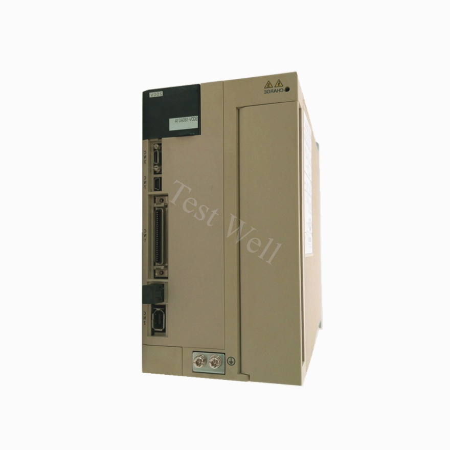
3. Ground Fault — GF
Fault Manifestation
The drive detects current leaking to ground during power-up or running.
Root Causes
- Water, coolant, or metal chips inside the motor junction box creating a ground path.
- Worn cable insulation chafed against conduit or cable chain.
- Internal drive ground-fault detection circuit drift (rare, but possible after years of heat cycling).
Step-by-Step Repair
- Disconnect all output wiring. If GF clears, the fault is downstream; if it persists, the drive itself needs inspection.
- Inspect the motor junction box and conduit entries; dry and seal any moisture ingress.
- Replace cables that show nicks, oil swelling, or green copper oxidation.
- After repair, run the drive at 10 % speed and monitor leakage current with a clamp-on ground-fault meter.
4. Overheat — oH (Heatsink Overheat)
Fault Manifestation
The heatsink thermistor reports a temperature above the safe operating limit (typically 90–100 °C depending on frame size).
Root Causes
- Blocked air filters or dust-packed heatsink fins.
- Cooling fan failure (bearing noise or no rotation).
- Ambient temperature above 40 °C without external ventilation.
- Excessive switching frequency (C6–01) set higher than the default, increasing switching losses.
Step-by-Step Repair
- Power down and let the drive cool. Remove the top/bottom covers and blow out the heatsink with dry compressed air (wear a dust mask).
- Spin each cooling fan blade by hand; replace any fan that grinds or does not free-spin.
- Verify cabinet intake and exhaust fans are running; add a cabinet fan if the ambient is consistently above 35 °C.
- Lower C6–01 to the default carrier frequency if you recently raised it.
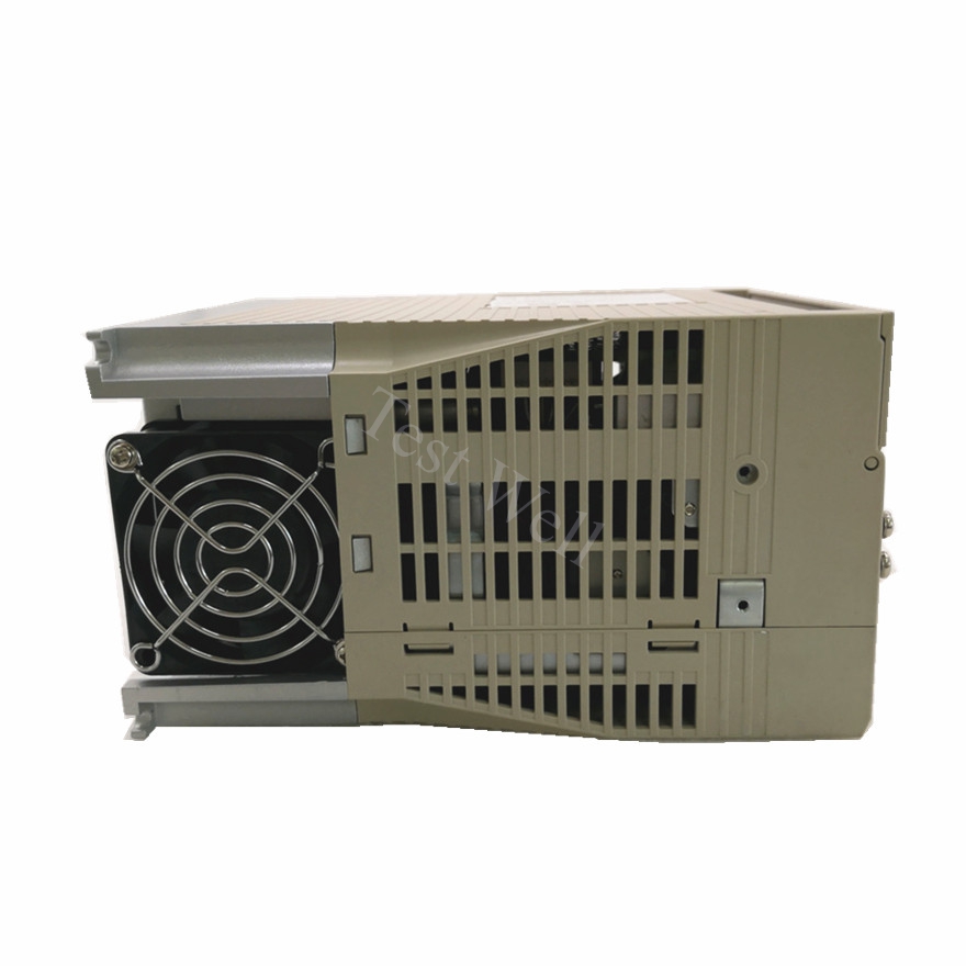
5. Overload — oL1 (Motor Overload) / oL2 (Drive Overload)
Fault Manifestation
oL1 trips when the electronic motor overload curve is exceeded; oL2 trips when the drive itself is thermally overloaded.
Root Causes
- Motor is undersized for the mechanical load (common after a process change).
- Drive capacity is one size too small for continuous heavy-duty cycles.
- Incorrect motor nameplate data entered in E1–E2 parameters.
- Mechanical binding, worn gearbox, or over-tensioned belt increasing torque demand.
Step-by-Step Repair
- Compare the actual load current (U1–03) to the motor rated current (E2–01). If U1–03 is consistently >105 %, the motor is too small.
- Check oL2 history: if it happens at low speed with high torque, you may need a drive one frame size larger or a blower-cooled motor.
- Verify E1–04 (max voltage) and E2–01 (rated current) match the motor nameplate exactly.
- Lubricate gearboxes and inspect belt tension; mechanical drag often masquerades as an electrical overload.
6. Undervoltage — Uv1 (Main Circuit Undervoltage)
Fault Manifestation
The DC bus drops below the undervoltage threshold while the run command is active.
Root Causes
- Weak mains or voltage sag during motor starting elsewhere on the same transformer.
- Blown input fuse or loose input terminal dropping one phase.
- DC bus capacitors aged and lost capacitance (common on drives >7 years old).
- Excessive cable length between the disconnect and the drive, causing voltage drop under load.
Step-by-Step Repair
- Monitor line voltage with a power quality analyzer during the fault event; look for sags >15 %.
- Tighten all input lugs to the manufacturer torque spec; check fuses with a multimeter.
- If the drive is old, measure DC bus capacitance with an ESR meter. Capacitance below 80 % of nominal means replacement or re-capping.
- Consider an active front-end or line reactor if the facility has chronic sag issues.
7. External Fault — EF / EF0
Fault Manifestation
The multi-function digital input programmed as "External Fault" (H1–xx = 20 or 20F) has been triggered by an upstream device.
Root Causes
- Thermal overload relay on the motor auxiliary circuit tripped.
- Emergency-stop string or safety gate opened.
- External PLC output driving the fault input due to a logic bug or sensor failure.
Step-by-Step Repair
- Check the external device that is wired to the digital input terminal; reset any thermal overloads.
- Review PLC logic to see if the fault bit is being set by a false sensor reading.
- Verify terminal wiring is shielded and grounded at one end only to prevent EMI-induced false EF trips.
8. Control Fault — CF (Control Circuit Error) / CPFxx (Control PCB Faults)
Fault Manifestation
CF indicates a control-circuit timing or communication error. CPF02–CPF35 point to specific control-board hardware or EEPROM issues.
Root Causes
- Corrupted parameter EEPROM after an incomplete write during a power dip.
- Control PCB connector loose after vibration or transportation.
- Defective control board or A/D converter circuit.
Step-by-Step Repair
- Record all parameter settings, then initialize the drive to factory defaults (A1–03 = 2220). Re-enter parameters manually; if the fault returns, the board is suspect.
- Reseat all internal ribbon cables and connectors on the control PCB.
- If CPF persists, replace the control PCB or the entire drive. Keep the old unit for spare power modules if the IGBTs test good.
9. Communication Fault — bUS (Option Card Comm Error) / CE (Modbus Comm Error)
Fault Manifestation
bUS appears when a communication option card (SI–C3, SI–N3, etc.) loses contact with the host. CE appears on built-in RS–485 Modbus/RTU links.
Root Causes
- Loose option card or back-plane connector.
- Incorrect baud rate, parity, or station address (H5–xx parameters).
- Excessive electrical noise on the RS–485 cable.
- Termination resistor missing at the end of the Modbus daisy chain.
Step-by-Step Repair
- Power down, remove and reseat the option card; inspect gold fingers for tarnish.
- Verify H5–01 (station address), H5–02 (baud), and H5–03 (parity) match the PLC/HMI settings.
- Use shielded twisted-pair cable; ground the shield at the master end only. Add a 120 Ω termination resistor at the last drive.
- If CE occurs only during VFD switching, add a ferrite core on the communication cable near the drive.
10. Preventive Maintenance Schedule
| Interval | Task |
|---|
| Monthly | Blow dust from heatsink and intake vents; check fan rotation. |
| Quarterly | Tighten power and control terminals; inspect cable insulation. |
| Semi-annually | Record DC bus voltage, output current, and heatsink temp trends. |
| Annually | Megger motor cables; verify braking resistor ohms; replace cooling fans proactively. |
| Every 5–7 years | Measure DC bus capacitor ESR; plan replacement before end-of-life. |
11. FAQ
Q: Can I clear a fault just by cycling power?
A: You can reset most faults, but if the root cause (short, overload, overheat) is still present, the drive will trip again immediately. Always diagnose first.
Q: Is the A1000 still supported for spare parts?
A: Yes. Yaskawa continues to supply A1000 power and control boards, although the GA700 series is the current successor. We stock compatible servo motors such as the SGM7J–08AFA61 and the SGMPH–04DAA61–OY for customers upgrading legacy axes.
Q: Do I need a line reactor with the A1000?
A: Yaskawa recommends a line reactor when the mains short-circuit capacity exceeds 100 kA or when multiple drives share one transformer. It also reduces input current harmonics and protects against utility transients.
Need a replacement drive, braking resistor, or servo motor? Contact Test Well Electronics Limited for stock availability and same-day shipping options.


